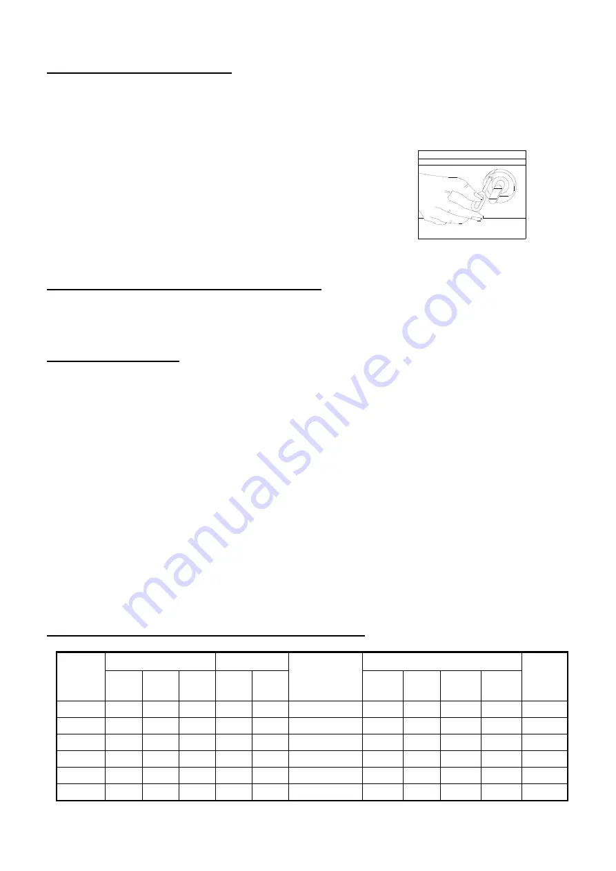
ADJUSTING MINIMUM FLOW
This operation must be carried out jointly with the primary air regulation.
Light the burner, rotate the knob to the minimum flow position and watch the flame. If any
adjustment is necessary, proceed as follows:
-
Remove the knob and, using a screwdriver, rotate
the regulator screw valve adjuster so that the flame is
steady and activates the thermocouple;
-
Check to see that when rotating the valve stem
quickly and back and forth between the maximum
and minimum flow position, the burner flame does
not go out.
ADAPTING TO DIFFERENT TYPES OF GAS
When converting from one type of gas to another, it is necessary to replace the burner injectors.
Read the tables entitled “Operating Pressures and Injectors”.
To replace the injectors:
-
Place the appliance upside down
-
In the back side of the appliance, dismantle the plaque that fixes the burner
-
Dismantle the burner
-
Substitute the injector that fits the required type of gas
-
Assemble the parts by doing the operations described above in reverse order
-
Put the appliance in its working position.
In any cases, always check the tightness of connections.
Proceed to regulate the primary air and the minimum as stated above.
The replacement injectors for converting to another type of gas are supplied with the
appliance.
The injectors come with a “WARNING” label, which should be used when the appliance is
converted to another type of gas.
GAS COOKING TABLE TOPS CHARACTERISTICS
Mod.
Size
Burner
Consumption
(kW)
Consumption Total
Plate
(mm)
H.
(mm)
W.
(mm)
D.
(mm)
2750
3400
G30
(kg/h)
G31
(kg/h)
G20
(m
3
/h)
G25
(m
3
/h)
1PL006
260
425
480
-
1
3,40
0,268
0,264
0,360
0,418
6
2PL006
260
625
480
2
-
5,50
0,434
0,426
0,582
0,676
6
3PL006
260
825
480
3
-
8,25
0,651
0,639
0,873
1,014
6
1PL014
305
425
480
-
1
3,40
0,268
0,264
0,360
0,418
14
2PL014
305
625
480
-
2
6,80
0,536
0,528
0,720
0,836
14
3PL014
305
825
480
-
3
10,20
0,804
0,792
1,080
1,254
14


