2 Instrument description
20
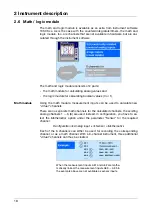
Logic module
There is also a maximum of 6 logic channels.
As is the case with all the other digital signals, the calculated digital (boolean)
values can be used for different functions:
- recording in the event traces,
- as an operating signal for display switch-off,
- time synchronization,
- timer,
- externally operated counters / integrators,
- counter/integr. reset,
- event operation and key inhibit,
- for output to a relay and
- as count input for a counter.
The following variables are available for the formulae:
- logic inputs
- logic channels
- alarms
- errors
- Modbus-Flag (signal via serial interface)
- TRUE
- FALSE
- instrument-specific data (only after consultation with the manufacturer)
The functions below can be used for the formulae:
- !
(NOT)
- &
(AND)
- |
(OR)
- ^
(XOR)
- /
(rising edge)
- \ (falling
edge)
- ( (open
bracket)
- ) (close
bracket)
H
For additional information, see
Chapter 5.4 “Math and logic module”
Summary of Contents for LOGOSCREEN 500
Page 1: ...Paperless recorder B 95 5015 Operating Instructions 04 02 00378469...
Page 2: ......
Page 6: ...Contents...
Page 48: ...3 Operation and visualization 46...
Page 66: ...4 Configuration parameters 64...
Page 76: ...5 Setup program 74...
Page 87: ...85 10 T V Report on Data Manipulation Security...
Page 88: ...10 T V Report on Data Manipulation Security 86...
Page 89: ...87 10 T V Report on Data Manipulation Security...
Page 90: ...10 T V Report on Data Manipulation Security 88...
Page 97: ......
Page 98: ......
Page 99: ......

