


18
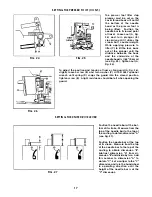
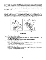
FIG. 28
FIG. 29
SETTING THE KNIFE DRIVE LEVER (CONT.)
At this time the knife drive lever should be in the 6 o'clock
position. If adjustment is necessary, loosen screws (A, Fig. 28)
in the needle lever and reposition knife drive lever (B) to the
6 o'clock position. Tighten screws (A). The dimension be-
tween the centerline of right and left knife drive connection
ball joints (C and D) must be 2 27/32" (72.2mm). Loosen left
hand thread nut (E), right hand thread nut (F) and turn con-
necting rod (G) until dimension is achieved. Tighten nuts (E
and F).
SETTING THE TRIMMING KNIVES FOR LAP SEAMING
(ALL STYLES )
To make the adjustments for a lap seam, position lower
knife (A, Fig. 29) in the foot so it extends 1/64" (0.4mm)
past the right side of the left toe (B) (approximately even
with the first needle). Loosen screw (C) and move knife
in or out as required. Tighten screw (C) securely.
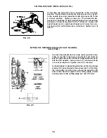
Turn handwheel in operating direction until knife driving
bracket (D) is positioned to the extreme left. At this time
the front edge of both knives should be parallel with
each other and the upper knife cutting edge should
overlap lower knife cutting edge by 1/64" (0.4mm).
Summary of Contents for UnionSpecial 36200UAD52
Page 7: ...7 THREADING 36200 0 0 MACHINE...
Page 22: ...22 9 16...
Page 24: ...24 2 31 18 17 14 ____ 12 19 4 3...
Page 26: ...26 3...
Page 28: ...28 21 T19DRQUE TO 21 22 241n lbs cm kg I...
Page 30: ...30 15 12 6 j 38 I I 44 37 28...
Page 40: ...40 4 40 i li l rrrt l 1 i r C J 4 12 2 27 32 172 2mml 3 5 32 180 2mmJ...
Page 44: ...44 16 27 Torque to 18 rt lbso I...
Page 46: ...46 11 3...
Page 48: ...48 1 17A...
Page 50: ...50...
Page 52: ...52 2 4 4 5 8 9 10 20 15 21 25...
Page 56: ...56 1 4...
Page 58: ...58 17 18 8 7 6...


