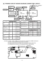


–
14
–
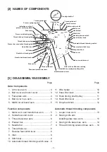
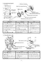
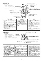
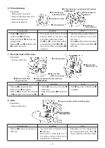
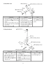
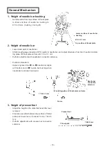
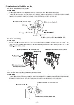
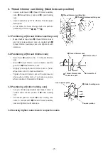
4. Thread trimmer solenoid mas. asm.
Preparation
○
Remove outer components.
(Remove arm cover asm., belt cover, motor
cover and cord guide.)
○
Remove solenoid cover.
○
Remove washer, E-ring and eccentric shaft of
thread trimmer solenoid link A.
❸
Thread trimmer solenoid
mas. asm. setscrew
SM5040655SN
❺
Moving knife
roller arm
❹
Moving knife arm
❶
Thread trimmer
solenoid link A
Washer and E-ring
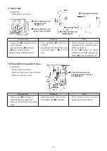
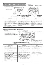
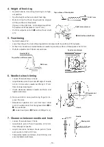
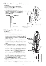
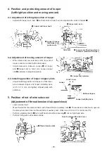
3. Moving knife base mas. asm.
Preparation
○
Remove bed cover.
○
Remove throat plate asm.
❶
Moving knife link
shaft A E-ring
❷
Moving knife
base mas. asm.
setscrew
SM4040855SP
❸
Feed dog
Eccentric shaft setscrew
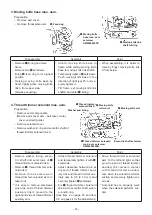
Disassembly
Assembly
Point
○
Remove washer, E-ring, eccen-
tric shaft and setscrews of
❶
thread trimmer solenoid link A.
○
Remove
❶
thread trimmer sole-
noid link A.
○
Remove three setscrews in
thread trimmer solenoid asm. to
take it out.
* It is easy to remove setscrews
when top end of thread trimmer
auxiliary link is moved to the
right-hand side of thread trimmer
auxiliary cam.
○
Attach thread trimmer solenoid
and temporarily tighten it with
❸
setscrews.
○
Adjust clearance between pin at
top end of thread trimmer auxil-
iary link and thread trimmer aux-
iliary cam to 0.5 to 1.0 mm and
securely tighten
❸
setscrews.
○
Fix
❶
thread trimmer solenoid
link A with eccentric shaft, wash-
er and E-ring.
(See item 2 on page 23 and item
3-5 on page 24 for the adjustment.)
○
Move thread trimmer solenoid
asm. to the left and right so that
pin at top end of thread trimmer
auxiliary link comes in contact
with thread trimmer auxiliary
cam when the solenoid performs
suction and securely tighten set-
screws.
* Solenoid has to properly work
when the solenoid performs suc-
tion.
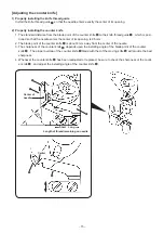
Disassembly
Assembly
Point
○
Remove
❶
E-ring and raise
frame.
○
Remove two
❷
setscrews.
○
Bring
❸
feed dog to its highest
position.
○
Raising moving knife base by
hand, lightly press moving knife
link A from upper side.
(Release coupling.)
○
Attach moving knife base to
frame while setting moving knife
base to moving knife link shaft A.
○
Temporarily tighten
❷
setscrews.
○
Push moving knife base in the
direction of right rear 45˚ and se
-
curely tighten it.
○
Tilt frame, set moving knife link
shaft A and enter
❶
E-ring.
○
When assembling, it is better to
raise by finger moving knife link
A from below.
Summary of Contents for TL Series
Page 31: ......