33
13.2
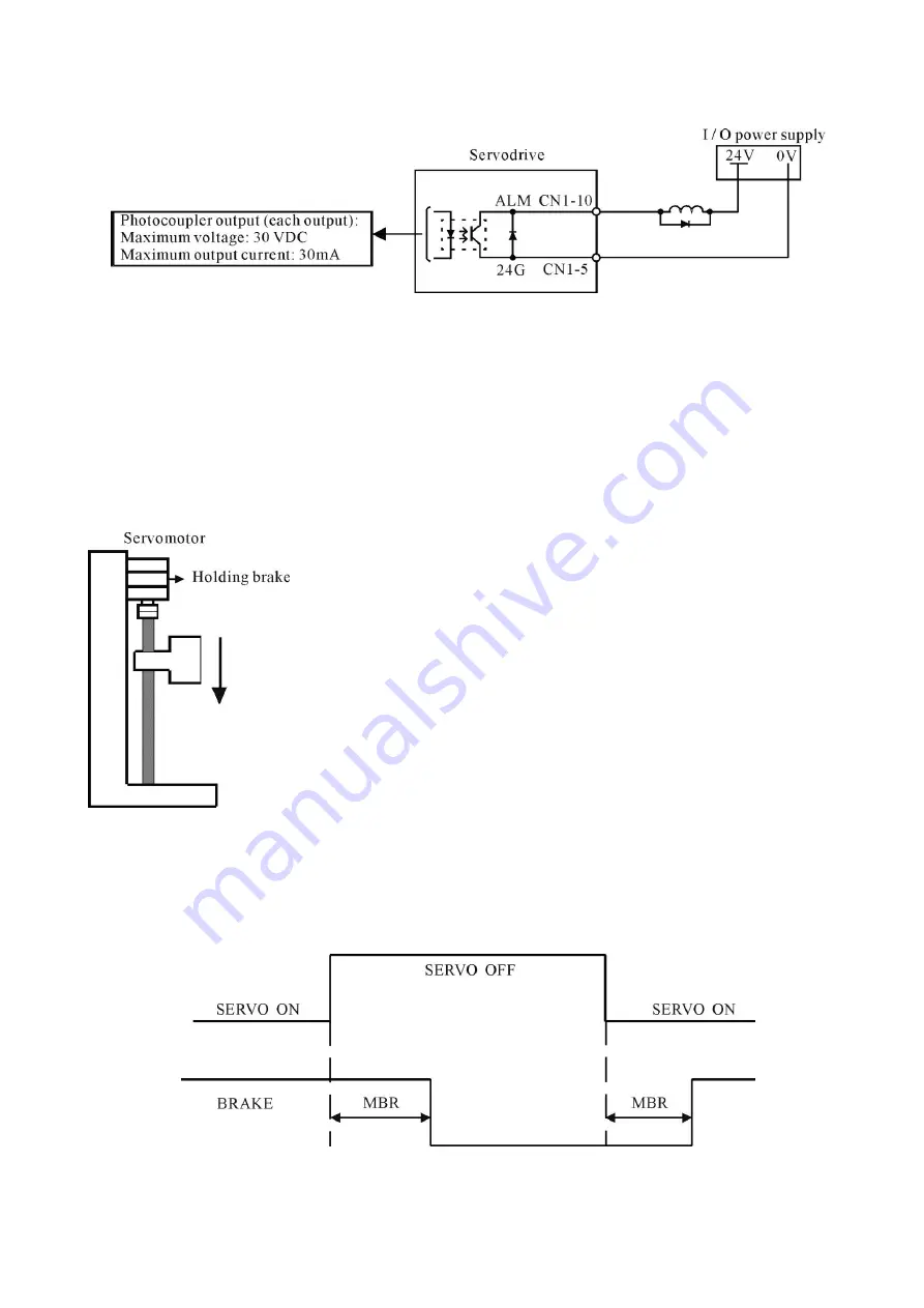
ALM Servo alarm output (CN1-10)
This signal indicates that an abnormal state of the servo drive occurs.
13.3
Brake motor brake release output (CN1-17)
If CN-17 is programmed as the brake release signal, when the driver is enabled through the contact of
SON (CN 1-6) and 24G, the brake release signal will be issued after a delay time defined by the MBR
parameter in the
“
Common Parameter
”
menu.
If CN-17 is programmed as the servo ready signal (default), after the driver is enabled and no alarm
has been detected, the servo ready signal will be issued immediately.
When the system power is turned off, the servomotor with
brake prevents the movable parts from dropping due to gravity.
The brake built in the servomotor is of passive type and is intended only for holding the motor and
cannot be used to actually stop a rotating motor. Be sure that the holding brake is applied after the motor is
stopped. The braking torque is at least 120% of the rated motor torque.
Summary of Contents for YPV-040
Page 21: ...20 8 2 Encoder digital output interface circuit...
Page 22: ...21 9 Position control interface...
Page 23: ...22 10 Speed control interface...
Page 24: ...23 11 Torque control interface...
Page 63: ...62 15 12 Online Monitor Use Read button to read the under monitoring data and stop to exit...
Page 69: ...68 20 Wiring of MPC3024 wiring board to Mokon driver...


