


PRECAUTIONS
vii
PRECAUTIONS
DANGER
Never carry out internal inspection or repair work of the equipment
by users.
Inspection or repair work by unauthorized personnel may result in
fire hazard or electric shock.
For inspection and repair work of equipment components, consult
with our branch office, branch shop, sales office, or our distributor
in your district.
When conducting maintenance, make sure to turn the main power
off.
Failure to comply may result in electrocution.
Turn off the main power before cleaning the equipment. Especially
when a rectifier is used, make sure to turn it off since voltage is
still output from the rectifier even after the radar is turned off.
Failure to comply may result in equipment failure, electric shock or
serious injury.
When conducting maintenance work on the antenna, make sure to
turn its main power off.
Failure to comply may result in electrocution or injuries.
Make sure to turn on the antenna operation switch.
Failure to comply may result in injuries caused by physical contact
with the rotating antenna.
Summary of Contents for JMA-3300 Series
Page 2: ......
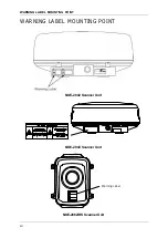
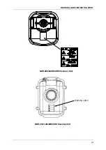
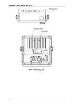
Page 16: ...WARNING LABEL MOUNTING POINT xiv NCD 2182 Display Unit ...
Page 17: ...WARNING LABEL MOUNTING POINT xv NBA 5111 Power Supply NBD 865 Rectifier unit ...
Page 30: ...GLOSSARY xxviii ...
Page 46: ...Chapter 1 GENERAL AND EQUIPMENT COMPOSITION 1 5 GENERAL SYSTEM DIAGRAMS 1 16 ...
Page 244: ...Chapter 4 MAINTENANCE 4 6 TROUBLE SHOOTING 4 36 ...
Page 266: ...APPENDIX APPENDIX 2 Fig A2 NKE 2043 SCANNER INTERCONNECTION DIAGRAM ...
Page 268: ...APPENDIX APPENDIX 4 Fig A4 NKE 2062HS SCANNER INTERCONNECTION DIAGRAM ...
Page 271: ...APPENDIX APPENDIX 7 APPENDIX INSTRUCTION MANUAL LJ 1 6 6 11 5 17 5 211 7 21 5 0 ...
Page 272: ...APPENDIX APPENDIX 8 Fig A8 NKE 2063AHS SCANNER INTERCONNECTION DIAGRAM ...
Page 274: ...APPENDIX APPENDIX Fig A NCD 2182 DISPLAY UNIT INTERCONNECTION DIAGRAM ...
Page 276: ...APPENDIX APPENDIX 1 Fig A1 JMA 3314 INTERCONNECTION DIAGRAM ...
Page 277: ...APPENDIX APPENDIX 1 APPENDIX INSTRUCTION MANUAL Fig A1 JMA 3334 INTERCONNECTION DIAGRAM ...
Page 278: ...APPENDIX APPENDIX 1 Fig A1 JMA 3316 HS INTERCONNECTION DIAGRAM ...
Page 280: ...APPENDIX APPENDIX 1 Fig A1 JMA 3340 4 4HS 6 6HS INTERCONNECTION DIAGRAM ...
Page 297: ......