


BEFORE OPERATION
vi
BEFORE OPERATION
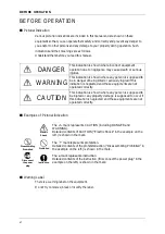
Pictorial Indication
Various pictorial indications are included in this manual and are shown on these
equipment so that you can operate them safety and correctly and prevent any danger to
you and/or to other persons and any damage to your property during operation. Such
indications and their meanings are as follows.
Understand them before you read this manual.
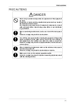
DANGER
This indication is shown where incorrect equipment
operation due to negligence may cause death or serious
injuries.
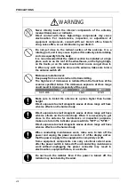
WARNING
This indication is shown where any person is supposed to
be in danger of being killed or seriously injured if this
indication is neglected and these equipments are not
operated correctly.
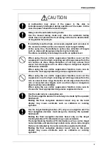
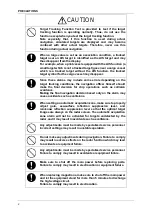
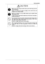
CAUTION
This indication is shown where any person is supposed to
be injured or any property damage is supposed to occur if
this indication is neglected and these equipments are not
operated correctly.
Examples of Pictorial Indication
Electric
Shock
The
ڹ
mark represents CAUTION (including DANGER and
WARNING).
Detailed contents of CAUTION ("Electric Shock" in the example on the
left.) is shown in the mark.
Disassembling
Prohibited
Prohibited
The
mark represents prohibition.
Detailed contents of the prohibited action ("Disassembling Prohibited" in
the example on the left.) is shown in the mark.
Disconnect
the power
plug
Instruction
7KHƔPDUNUHSUHVHQWVLQVWUXFWLRQ
Detailed contents of the instruction ("Disconnect the power plug" in the
example on the left.) is shown in the mark.
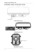
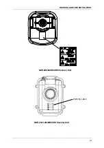
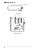
Warning Label
There is a warning label on the equipment.
Do not try to remove, break or modify the label.
Summary of Contents for JMA-3300 Series
Page 2: ......
Page 16: ...WARNING LABEL MOUNTING POINT xiv NCD 2182 Display Unit ...
Page 17: ...WARNING LABEL MOUNTING POINT xv NBA 5111 Power Supply NBD 865 Rectifier unit ...
Page 30: ...GLOSSARY xxviii ...
Page 46: ...Chapter 1 GENERAL AND EQUIPMENT COMPOSITION 1 5 GENERAL SYSTEM DIAGRAMS 1 16 ...
Page 244: ...Chapter 4 MAINTENANCE 4 6 TROUBLE SHOOTING 4 36 ...
Page 266: ...APPENDIX APPENDIX 2 Fig A2 NKE 2043 SCANNER INTERCONNECTION DIAGRAM ...
Page 268: ...APPENDIX APPENDIX 4 Fig A4 NKE 2062HS SCANNER INTERCONNECTION DIAGRAM ...
Page 271: ...APPENDIX APPENDIX 7 APPENDIX INSTRUCTION MANUAL LJ 1 6 6 11 5 17 5 211 7 21 5 0 ...
Page 272: ...APPENDIX APPENDIX 8 Fig A8 NKE 2063AHS SCANNER INTERCONNECTION DIAGRAM ...
Page 274: ...APPENDIX APPENDIX Fig A NCD 2182 DISPLAY UNIT INTERCONNECTION DIAGRAM ...
Page 276: ...APPENDIX APPENDIX 1 Fig A1 JMA 3314 INTERCONNECTION DIAGRAM ...
Page 277: ...APPENDIX APPENDIX 1 APPENDIX INSTRUCTION MANUAL Fig A1 JMA 3334 INTERCONNECTION DIAGRAM ...
Page 278: ...APPENDIX APPENDIX 1 Fig A1 JMA 3316 HS INTERCONNECTION DIAGRAM ...
Page 280: ...APPENDIX APPENDIX 1 Fig A1 JMA 3340 4 4HS 6 6HS INTERCONNECTION DIAGRAM ...
Page 297: ......