


Chapter 2
OPERATIONS
2.7
SOFT KEY OPERATION
2-14
2.7
SOFT KEY OPERATION
This radar can be operated with the soft keys and the MULTI control placed on the front
panel of the display unit. You can access to functions without opening the menu screen.
To change the default settings, press the
[MENU]
key to open the menu screen.
This section describes the operation with the soft keys and the MULTI control.
Keys for operation
y
Soft keys 1, 2, 3 and 4
y
[MULTI]
control
y
[CLEAR]
key
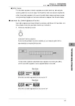
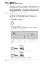
Soft Key Operations (Example: Opening "Display Screen")
This section describes how to operate with the soft keys shown below.
y
TUNE/PRF
y
Display Screen
y
TM/RM
y
Bearing Mode
y
Pulse Length
y
Off Center
y
Symbol Display
y
MOB
y
Mark
y
Line
y
Own Track
y
Event Mark
y
AIS Filter
y
TLL TX
Summary of Contents for JMA-3300 Series
Page 2: ......
Page 16: ...WARNING LABEL MOUNTING POINT xiv NCD 2182 Display Unit ...
Page 17: ...WARNING LABEL MOUNTING POINT xv NBA 5111 Power Supply NBD 865 Rectifier unit ...
Page 30: ...GLOSSARY xxviii ...
Page 46: ...Chapter 1 GENERAL AND EQUIPMENT COMPOSITION 1 5 GENERAL SYSTEM DIAGRAMS 1 16 ...
Page 244: ...Chapter 4 MAINTENANCE 4 6 TROUBLE SHOOTING 4 36 ...
Page 266: ...APPENDIX APPENDIX 2 Fig A2 NKE 2043 SCANNER INTERCONNECTION DIAGRAM ...
Page 268: ...APPENDIX APPENDIX 4 Fig A4 NKE 2062HS SCANNER INTERCONNECTION DIAGRAM ...
Page 271: ...APPENDIX APPENDIX 7 APPENDIX INSTRUCTION MANUAL LJ 1 6 6 11 5 17 5 211 7 21 5 0 ...
Page 272: ...APPENDIX APPENDIX 8 Fig A8 NKE 2063AHS SCANNER INTERCONNECTION DIAGRAM ...
Page 274: ...APPENDIX APPENDIX Fig A NCD 2182 DISPLAY UNIT INTERCONNECTION DIAGRAM ...
Page 276: ...APPENDIX APPENDIX 1 Fig A1 JMA 3314 INTERCONNECTION DIAGRAM ...
Page 277: ...APPENDIX APPENDIX 1 APPENDIX INSTRUCTION MANUAL Fig A1 JMA 3334 INTERCONNECTION DIAGRAM ...
Page 278: ...APPENDIX APPENDIX 1 Fig A1 JMA 3316 HS INTERCONNECTION DIAGRAM ...
Page 280: ...APPENDIX APPENDIX 1 Fig A1 JMA 3340 4 4HS 6 6HS INTERCONNECTION DIAGRAM ...
Page 297: ......