


APPENDIX
APPENDIX-2
EU Declaration Of Conformity
1) Apparatus Product/Model:
Product: Marine Radar.
Model: JMA-3300 Series
(JMA-3334/3336/3336HS/3340-4/3340-4HS/3340-6/3340-6HS)
2) Name & Address of the Manufacturer:
Japan Radio Co., Ltd.,
21-11, Mure 6-chome, Mitaka-shi, Tokyo 181-0002 Japan.
3) This declaration of conformity is issued under the sole responsibility of the manufacturer.
4) Object of the declaration – identification of apparatus allowing traceability:
࣭
Marine Radar, Japan Radio Co., Ltd manufactured model JMA-3334.
࣭
Marine Radar, Japan Radio Co., Ltd manufactured model JMA-3336.
࣭
Marine Radar, Japan Radio Co., Ltd manufactured model JMA-3336HS.
࣭
Marine Radar, Japan Radio Co., Ltd manufactured model JMA-3340-4.
࣭
Marine Radar, Japan Radio Co., Ltd manufactured model JMA-3340-4HS.
࣭
Marine Radar, Japan Radio Co., Ltd manufactured model JMA-3340-6.
࣭
Marine Radar, Japan Radio Co., Ltd manufactured model JMA-3340-6HS.
5) The object of the declaration described above is in conformity with the relevant EU
harmonization legislation:
Radio Equipment Directive (RED): 2014/53/EU.
6) References to the relevant harmonized standards used, including the date of the standard,
or references to other technical specifications, including the date of the specification, in
relation to which conformity is declared:
EN60945:2002 (Ed4) - General Requirements for Marine Equipment.
ETSI EN 302 248 (v2.1.1) – Navigation radar for use on non-SOLAS vessels.
IEC61162 series – as applicable.
7) Notified Body involved:
Not applicable.
IN
STR
U
C
TIO
N
MA
N
UA
L
AP
PENDI
X
Summary of Contents for JMA-3300 Series
Page 2: ......
Page 16: ...WARNING LABEL MOUNTING POINT xiv NCD 2182 Display Unit ...
Page 17: ...WARNING LABEL MOUNTING POINT xv NBA 5111 Power Supply NBD 865 Rectifier unit ...
Page 30: ...GLOSSARY xxviii ...
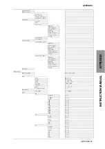
Page 46: ...Chapter 1 GENERAL AND EQUIPMENT COMPOSITION 1 5 GENERAL SYSTEM DIAGRAMS 1 16 ...
Page 244: ...Chapter 4 MAINTENANCE 4 6 TROUBLE SHOOTING 4 36 ...
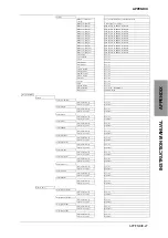
Page 266: ...APPENDIX APPENDIX 2 Fig A2 NKE 2043 SCANNER INTERCONNECTION DIAGRAM ...
Page 268: ...APPENDIX APPENDIX 4 Fig A4 NKE 2062HS SCANNER INTERCONNECTION DIAGRAM ...
Page 271: ...APPENDIX APPENDIX 7 APPENDIX INSTRUCTION MANUAL LJ 1 6 6 11 5 17 5 211 7 21 5 0 ...
Page 272: ...APPENDIX APPENDIX 8 Fig A8 NKE 2063AHS SCANNER INTERCONNECTION DIAGRAM ...
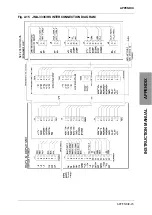
Page 274: ...APPENDIX APPENDIX Fig A NCD 2182 DISPLAY UNIT INTERCONNECTION DIAGRAM ...
Page 276: ...APPENDIX APPENDIX 1 Fig A1 JMA 3314 INTERCONNECTION DIAGRAM ...
Page 277: ...APPENDIX APPENDIX 1 APPENDIX INSTRUCTION MANUAL Fig A1 JMA 3334 INTERCONNECTION DIAGRAM ...
Page 278: ...APPENDIX APPENDIX 1 Fig A1 JMA 3316 HS INTERCONNECTION DIAGRAM ...
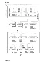
Page 280: ...APPENDIX APPENDIX 1 Fig A1 JMA 3340 4 4HS 6 6HS INTERCONNECTION DIAGRAM ...
Page 297: ......