


GLOSSARY
xxiv
E
EBL
Electronic Bearing Line
An electronic bearing line originated from own ship’s position.
ENH
Enhance
ETA
Estimated Time of Arrival
G
Ground stabilization
A display mode in which speed and course information are referred to the ground, using
ground track input data.
H
HDG
Heading
The horizontal direction that the bow of a ship is pointing at any instant, expressed in
angular units from a reference direction .
HL
Heading line
A graphic line on a radar presentation drawn from the consistent common reference
point to the bearing scale to indicate the heading of the ship
H up
Head up
Own ship’s heading line is always pointed to the top center of the radar display.
I
IR
Radar Interference Rejecter
L
Lost AIS target
A target symbol representing the last valid position of an AIS target before the reception
of its data was lost, or its last dead-reckoned position.
Lost tracked target
One for which target information is no longer available due to poor, lost or obscured
signals.
LP
Long Pulse
M
MMSI
Maritime Mobile Service Identity
MOB
Man OverBoard
MP
Medium Pulse
N
NM
1NM=1852m
NSK
North Stabilization Kit
N up
North up
The north is always pointed to the top center of the radar display.
O
Own track
Display function of own ship’s track
Summary of Contents for JMA-3300 Series
Page 2: ......
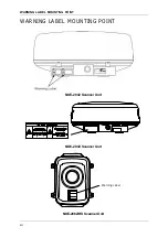
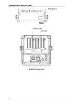
Page 16: ...WARNING LABEL MOUNTING POINT xiv NCD 2182 Display Unit ...
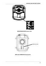
Page 17: ...WARNING LABEL MOUNTING POINT xv NBA 5111 Power Supply NBD 865 Rectifier unit ...
Page 30: ...GLOSSARY xxviii ...
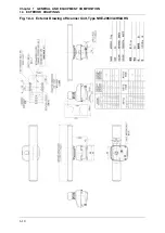
Page 46: ...Chapter 1 GENERAL AND EQUIPMENT COMPOSITION 1 5 GENERAL SYSTEM DIAGRAMS 1 16 ...
Page 244: ...Chapter 4 MAINTENANCE 4 6 TROUBLE SHOOTING 4 36 ...
Page 266: ...APPENDIX APPENDIX 2 Fig A2 NKE 2043 SCANNER INTERCONNECTION DIAGRAM ...
Page 268: ...APPENDIX APPENDIX 4 Fig A4 NKE 2062HS SCANNER INTERCONNECTION DIAGRAM ...
Page 271: ...APPENDIX APPENDIX 7 APPENDIX INSTRUCTION MANUAL LJ 1 6 6 11 5 17 5 211 7 21 5 0 ...
Page 272: ...APPENDIX APPENDIX 8 Fig A8 NKE 2063AHS SCANNER INTERCONNECTION DIAGRAM ...
Page 274: ...APPENDIX APPENDIX Fig A NCD 2182 DISPLAY UNIT INTERCONNECTION DIAGRAM ...
Page 276: ...APPENDIX APPENDIX 1 Fig A1 JMA 3314 INTERCONNECTION DIAGRAM ...
Page 277: ...APPENDIX APPENDIX 1 APPENDIX INSTRUCTION MANUAL Fig A1 JMA 3334 INTERCONNECTION DIAGRAM ...
Page 278: ...APPENDIX APPENDIX 1 Fig A1 JMA 3316 HS INTERCONNECTION DIAGRAM ...
Page 280: ...APPENDIX APPENDIX 1 Fig A1 JMA 3340 4 4HS 6 6HS INTERCONNECTION DIAGRAM ...
Page 297: ......