


Chapter 5
AFTER-SALES SERVICE
5.1
KEEPING PERIOD OF MAINTENANCE PARTS
5-1
5
INS
TRUCT
IO
N
M
ANUAL
Chapter 5
AFTER-SALES SERVICE
5.1
KEEPING PERIOD OF MAINTENANCE PARTS
Keeping period of maintenance parts is ten years from the production is discontinued.
5.2
WHEN YOU REQUEST FOR REPAIR
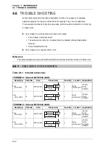
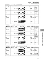
If you suppose the product may be out of order, read the description in "4.5 FAULT
FINDING" and "4.6 TROUBLE SHOOTING", and check the suspected point again.
If it is still out of order, you are recommended to stop operation of the equipment and
consult with the dealer from whom you purchased the product, or our branch office in
your country or district, the sales department in our main office in Tokyo.
z
Repair within the Warranty Period
If any failure occurs in the product during its
normal operation in accordance with the instruction manual, the dealer or JRC will
repair free of charge. In case that any failure is caused due to misuse, faulty
operation, negligence or force major such as natural disaster and fire, the product
will be repaired with charges.
z
Repair after the Warranty Period
If any defective function of the product is
recoverable by repair, the repair of it will be made at your own charge upon your
request.
z
Necessary Information for Repair
ۼ
Product name, model, manufacturing date and serial number
ۼ
Trouble conditions (as detailed as possible. Refer to page 5-2 "
Radar Failure
Check List".)
ۼ
Name of company/organization, address and telephone number
5.3
RECOMMENDED MAINTENANCE
The performance of the product may deteriorate due to the secular change of the parts
used in it, though such deterioration depends upon the conditions of operation.
So checkup and maintenance is recommendable for the product in addition to your daily
care.
For maintenance, consult with the near-by dealer or our sales department.
Such maintenance will be made with charges.
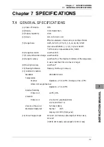
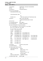
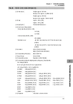
Summary of Contents for JMA-3300 Series
Page 2: ......
Page 16: ...WARNING LABEL MOUNTING POINT xiv NCD 2182 Display Unit ...
Page 17: ...WARNING LABEL MOUNTING POINT xv NBA 5111 Power Supply NBD 865 Rectifier unit ...
Page 30: ...GLOSSARY xxviii ...
Page 46: ...Chapter 1 GENERAL AND EQUIPMENT COMPOSITION 1 5 GENERAL SYSTEM DIAGRAMS 1 16 ...
Page 244: ...Chapter 4 MAINTENANCE 4 6 TROUBLE SHOOTING 4 36 ...
Page 266: ...APPENDIX APPENDIX 2 Fig A2 NKE 2043 SCANNER INTERCONNECTION DIAGRAM ...
Page 268: ...APPENDIX APPENDIX 4 Fig A4 NKE 2062HS SCANNER INTERCONNECTION DIAGRAM ...
Page 271: ...APPENDIX APPENDIX 7 APPENDIX INSTRUCTION MANUAL LJ 1 6 6 11 5 17 5 211 7 21 5 0 ...
Page 272: ...APPENDIX APPENDIX 8 Fig A8 NKE 2063AHS SCANNER INTERCONNECTION DIAGRAM ...
Page 274: ...APPENDIX APPENDIX Fig A NCD 2182 DISPLAY UNIT INTERCONNECTION DIAGRAM ...
Page 276: ...APPENDIX APPENDIX 1 Fig A1 JMA 3314 INTERCONNECTION DIAGRAM ...
Page 277: ...APPENDIX APPENDIX 1 APPENDIX INSTRUCTION MANUAL Fig A1 JMA 3334 INTERCONNECTION DIAGRAM ...
Page 278: ...APPENDIX APPENDIX 1 Fig A1 JMA 3316 HS INTERCONNECTION DIAGRAM ...
Page 280: ...APPENDIX APPENDIX 1 Fig A1 JMA 3340 4 4HS 6 6HS INTERCONNECTION DIAGRAM ...
Page 297: ......