


Chapter 4
MAINTENANCE
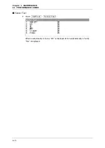
4.6
TROUBLE SHOOTING
4-30
4.6
TROUBLE SHOOTING
As this radar equipment includes complicated circuits, it is necessary to request a
specialist engineer for repair or instructions for remedy if any circuit is defective.
There are also troubles by the following causes, which should be referred to in checking
or repair work.
z
Poor Contact in Terminal Board of Inter-Unit Cables
y
Poor contact in terminal board
y
The cable end is not fully connected, that it, contacted with earthed another
terminal.
y
Disconnected cable wire
z
Poor Contact of Connector within Unit
Reference:
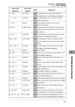
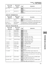
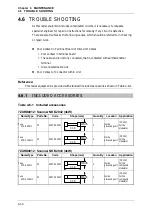
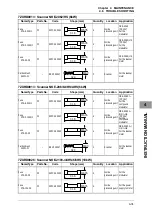
This radar equipment is provided with standard included accessories shown in Table 4.6-1.
4.6.1
INCLUDED ACCESSORIES
Table 4.6-1 Included accessories
7ZXRD0012 : Scanner NKE-2042 (4kW)
Name/Type Parts No.
Code
Shape (mm)
Quantity Location Application
Fuse
ST4-6.3AN1
F2
5ZFCA00051
4
Inside
processing unit
(DC12V)
For the
modulator
Fuse
ST4-3.15AN1
F2
5ZFCA00047
4
Inside
processing unit
(DC24V)
For the
modulator
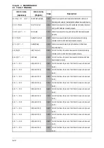
7ZXRD0012 : Scanner NKE-2043 (4kW)
Name/Type Parts No.
Code
Shape (mm)
Quantity Location Application
Fuse
ST4-6.3AN1
F2
5ZFCA00051
4
Inside
processing unit
(DC12V)
For the
compound
modulator
Fuse
ST4-3.15AN1
F2
5ZFCA00047
4
Inside
processing unit
(DC24V)
For the
compound
modulator
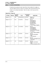
31.8
ĭ
6.35
31.8
ĭ
6.35
31.8
ĭ
6.35
31.8
ĭ
6.35
Summary of Contents for JMA-3300 Series
Page 2: ......
Page 16: ...WARNING LABEL MOUNTING POINT xiv NCD 2182 Display Unit ...
Page 17: ...WARNING LABEL MOUNTING POINT xv NBA 5111 Power Supply NBD 865 Rectifier unit ...
Page 30: ...GLOSSARY xxviii ...
Page 46: ...Chapter 1 GENERAL AND EQUIPMENT COMPOSITION 1 5 GENERAL SYSTEM DIAGRAMS 1 16 ...
Page 244: ...Chapter 4 MAINTENANCE 4 6 TROUBLE SHOOTING 4 36 ...
Page 266: ...APPENDIX APPENDIX 2 Fig A2 NKE 2043 SCANNER INTERCONNECTION DIAGRAM ...
Page 268: ...APPENDIX APPENDIX 4 Fig A4 NKE 2062HS SCANNER INTERCONNECTION DIAGRAM ...
Page 271: ...APPENDIX APPENDIX 7 APPENDIX INSTRUCTION MANUAL LJ 1 6 6 11 5 17 5 211 7 21 5 0 ...
Page 272: ...APPENDIX APPENDIX 8 Fig A8 NKE 2063AHS SCANNER INTERCONNECTION DIAGRAM ...
Page 274: ...APPENDIX APPENDIX Fig A NCD 2182 DISPLAY UNIT INTERCONNECTION DIAGRAM ...
Page 276: ...APPENDIX APPENDIX 1 Fig A1 JMA 3314 INTERCONNECTION DIAGRAM ...
Page 277: ...APPENDIX APPENDIX 1 APPENDIX INSTRUCTION MANUAL Fig A1 JMA 3334 INTERCONNECTION DIAGRAM ...
Page 278: ...APPENDIX APPENDIX 1 Fig A1 JMA 3316 HS INTERCONNECTION DIAGRAM ...
Page 280: ...APPENDIX APPENDIX 1 Fig A1 JMA 3340 4 4HS 6 6HS INTERCONNECTION DIAGRAM ...
Page 297: ......