


Chapter 4
MAINTENANCE
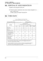
4.5
FAULT FINDING
4-26
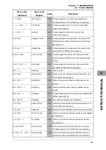
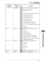
Alarm name
(Japanese)
Alarm name
(English)
Class
Description
᪉
/
⦋ᗘ⤒ᗘ ↓ࡋ
No HDG/POSN Data
Status Cursor operations when own heading or latitude/longitude is
disabled
y
MOB input
y
Event mark input
y
Inputting/erasing/moving marks
y
Inputting/erasing/moving/inserting lines
y
Floating position setting for EBL latitude/longitude.
y
Floating position setting for VRM latitude/longitude.
y
Floating position setting for parallel cursor latitude/longitude
y
AIS numerical display/destination ship/retrieved vessel
selection
y
Creating latitude/longitude alarm area.
y
TLL transmission for cursor.
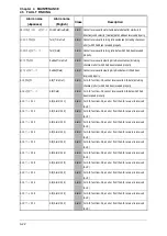
࡛ࡁࡲࡏࢇ
Not Allowed
Status
y
Operations for inserting by selecting the end point in the line
list.
y
Operations for switching to H-UP during TM
(When heading is not available, temporarily changed to
RM-HUp, therefore, message is disabled.)
タᐃྍ࡞ࣞࣥࢪ࡛ࡍ
Range Scale Limit
Status Operations functionally restricted for certain range.
y
Zoom operations in range where zoom is not available.
y
Off center operations in range where off center is not available.
y
TM setting operations in range where TM setting is not
available.
ࢹ࣮ࢱࡀ࠶ࡾࡲࡏࢇ
No Valid Data
Status Operations without data.
y
Displaying history menu without history data.
y
Operations for editing/erasing in the mark list while there is no
mark.
y
Operations for editing/erasing/inserting in the line list while
there is no line.
Summary of Contents for JMA-3300 Series
Page 2: ......
Page 16: ...WARNING LABEL MOUNTING POINT xiv NCD 2182 Display Unit ...
Page 17: ...WARNING LABEL MOUNTING POINT xv NBA 5111 Power Supply NBD 865 Rectifier unit ...
Page 30: ...GLOSSARY xxviii ...
Page 46: ...Chapter 1 GENERAL AND EQUIPMENT COMPOSITION 1 5 GENERAL SYSTEM DIAGRAMS 1 16 ...
Page 244: ...Chapter 4 MAINTENANCE 4 6 TROUBLE SHOOTING 4 36 ...
Page 266: ...APPENDIX APPENDIX 2 Fig A2 NKE 2043 SCANNER INTERCONNECTION DIAGRAM ...
Page 268: ...APPENDIX APPENDIX 4 Fig A4 NKE 2062HS SCANNER INTERCONNECTION DIAGRAM ...
Page 271: ...APPENDIX APPENDIX 7 APPENDIX INSTRUCTION MANUAL LJ 1 6 6 11 5 17 5 211 7 21 5 0 ...
Page 272: ...APPENDIX APPENDIX 8 Fig A8 NKE 2063AHS SCANNER INTERCONNECTION DIAGRAM ...
Page 274: ...APPENDIX APPENDIX Fig A NCD 2182 DISPLAY UNIT INTERCONNECTION DIAGRAM ...
Page 276: ...APPENDIX APPENDIX 1 Fig A1 JMA 3314 INTERCONNECTION DIAGRAM ...
Page 277: ...APPENDIX APPENDIX 1 APPENDIX INSTRUCTION MANUAL Fig A1 JMA 3334 INTERCONNECTION DIAGRAM ...
Page 278: ...APPENDIX APPENDIX 1 Fig A1 JMA 3316 HS INTERCONNECTION DIAGRAM ...
Page 280: ...APPENDIX APPENDIX 1 Fig A1 JMA 3340 4 4HS 6 6HS INTERCONNECTION DIAGRAM ...
Page 297: ......