


Chapter 4
MAINTENANCE
4.2
MAINTENANCE ON EACH UNIT
4-5
4
INS
TRUCT
IO
N
M
ANUAL
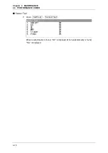
Table 4.2-1 List of replacement carbon brushes
Scanner unit
model name
Item name
Model name
JRC code
Replacement
quantity
JMA-3316
Carbon brush
54531-01
BRXP05247
2
JMA-3336
Carbon brush
54531-01
BRXP05247
2
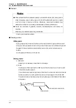
Mounting legs
Check the mounting legs and mounting bolts of the scanner unit case for corrosion at
intervals and maintain them to prevent danger. Apply paint to them once a half year
because painting is the best measure against corrosion.
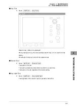
4.2.2
DISPLAY UNIT NCD-2182
WARNING
When cleaning the display screen, do not wipe it too strongly with
a dry cloth. Also, do not use gasoline or thinner to clean the
screen.
Failure to comply will result in damage to the screen surface.
Dust accumulated on the screen will reduce clarity and darken the video.
For cleaning it, wipe it with a piece of soft cloth (flannel or cotton). Do not wipe it
strongly with a piece of dry cloth nor use gasoline or thinner.
Summary of Contents for JMA-3300 Series
Page 2: ......
Page 16: ...WARNING LABEL MOUNTING POINT xiv NCD 2182 Display Unit ...
Page 17: ...WARNING LABEL MOUNTING POINT xv NBA 5111 Power Supply NBD 865 Rectifier unit ...
Page 30: ...GLOSSARY xxviii ...
Page 46: ...Chapter 1 GENERAL AND EQUIPMENT COMPOSITION 1 5 GENERAL SYSTEM DIAGRAMS 1 16 ...
Page 244: ...Chapter 4 MAINTENANCE 4 6 TROUBLE SHOOTING 4 36 ...
Page 266: ...APPENDIX APPENDIX 2 Fig A2 NKE 2043 SCANNER INTERCONNECTION DIAGRAM ...
Page 268: ...APPENDIX APPENDIX 4 Fig A4 NKE 2062HS SCANNER INTERCONNECTION DIAGRAM ...
Page 271: ...APPENDIX APPENDIX 7 APPENDIX INSTRUCTION MANUAL LJ 1 6 6 11 5 17 5 211 7 21 5 0 ...
Page 272: ...APPENDIX APPENDIX 8 Fig A8 NKE 2063AHS SCANNER INTERCONNECTION DIAGRAM ...
Page 274: ...APPENDIX APPENDIX Fig A NCD 2182 DISPLAY UNIT INTERCONNECTION DIAGRAM ...
Page 276: ...APPENDIX APPENDIX 1 Fig A1 JMA 3314 INTERCONNECTION DIAGRAM ...
Page 277: ...APPENDIX APPENDIX 1 APPENDIX INSTRUCTION MANUAL Fig A1 JMA 3334 INTERCONNECTION DIAGRAM ...
Page 278: ...APPENDIX APPENDIX 1 Fig A1 JMA 3316 HS INTERCONNECTION DIAGRAM ...
Page 280: ...APPENDIX APPENDIX 1 Fig A1 JMA 3340 4 4HS 6 6HS INTERCONNECTION DIAGRAM ...
Page 297: ......