


Chapter 4
MAINTENANCE
4.2
MAINTENANCE ON EACH UNIT
4-2
4.2
MAINTENANCE ON EACH UNIT
4.2.1
SCANNER UNIT NKE-2042,
2043,
2062/HS,
2063/HS,
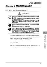
DANGER
When conducting maintenance work on the antenna, make sure to
turn its main power off.
Failure to comply may result in electrocution or injuries.
Make sure to turn off the antenna operation switch.
Failure to comply may result in injuries caused by physical contact
with the rotating antenna.
Do not touch the radiator. Even if the power is turned off, the
radiator may be rotated by the wind.
After the work, turn "ON" the scanner unit safety switch.
Precautions in Mounting the Cover
When the cover is removed for regular checkup and replacement of parts and refitted after
such work, the procedures of fastening bolts shall be taken with the following precautions:
y
The proper fastening torque of the fitting bolts (M8) is 1176 to 1470 N•cm (120 to
150kgf•cm) (which makes the inside water-tight and protects the packings against
permanent compressive strain). The packings start producing from the cover at a
torque of approximately 1470N•cm (150kgf•cm). Do not fasten the bolts with a
torque exceeding the specified value. Otherwise, the screws may be broken.
y
Use an offset wrench of 11 mm × 13 mm or a double-ended wrench of 13 mm × 17
mm (not longer than 200 mm).
y
Screw all the bolts by hand first to prevent them playing, then fasten them evenly in
order not to cause one-sided fastening. (Fasten the bolts with 25% of the required
torque at the first step.)
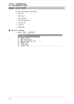
*: Fasten the bolts in the diagonal order.
ճ
ն
ձ
մ
յ
ղ
NKE-2042 Cover Bolt
Tightening Procedure
4-M5 (stainless steel) bolt
Tightening torque: 120 to 150 kgf/cm
2
$+6$+6+6+6
Summary of Contents for JMA-3300 Series
Page 2: ......
Page 16: ...WARNING LABEL MOUNTING POINT xiv NCD 2182 Display Unit ...
Page 17: ...WARNING LABEL MOUNTING POINT xv NBA 5111 Power Supply NBD 865 Rectifier unit ...
Page 30: ...GLOSSARY xxviii ...
Page 46: ...Chapter 1 GENERAL AND EQUIPMENT COMPOSITION 1 5 GENERAL SYSTEM DIAGRAMS 1 16 ...
Page 244: ...Chapter 4 MAINTENANCE 4 6 TROUBLE SHOOTING 4 36 ...
Page 266: ...APPENDIX APPENDIX 2 Fig A2 NKE 2043 SCANNER INTERCONNECTION DIAGRAM ...
Page 268: ...APPENDIX APPENDIX 4 Fig A4 NKE 2062HS SCANNER INTERCONNECTION DIAGRAM ...
Page 271: ...APPENDIX APPENDIX 7 APPENDIX INSTRUCTION MANUAL LJ 1 6 6 11 5 17 5 211 7 21 5 0 ...
Page 272: ...APPENDIX APPENDIX 8 Fig A8 NKE 2063AHS SCANNER INTERCONNECTION DIAGRAM ...
Page 274: ...APPENDIX APPENDIX Fig A NCD 2182 DISPLAY UNIT INTERCONNECTION DIAGRAM ...
Page 276: ...APPENDIX APPENDIX 1 Fig A1 JMA 3314 INTERCONNECTION DIAGRAM ...
Page 277: ...APPENDIX APPENDIX 1 APPENDIX INSTRUCTION MANUAL Fig A1 JMA 3334 INTERCONNECTION DIAGRAM ...
Page 278: ...APPENDIX APPENDIX 1 Fig A1 JMA 3316 HS INTERCONNECTION DIAGRAM ...
Page 280: ...APPENDIX APPENDIX 1 Fig A1 JMA 3340 4 4HS 6 6HS INTERCONNECTION DIAGRAM ...
Page 297: ......