


Chapter 2
OPERATIONS
2.15
SETTING TT/AIS
2-125
2
INS
TRUCT
IO
N
M
ANUA
L
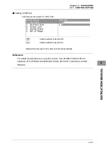
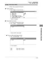
Setting CPA Ring
Sets the CPA ring display.
Off
:
The CPA ring is not displayed.
On
:
The CPA ring is displayed.
While the distance of the specified CPA Limit value is used as the radius, the CPA
ring is displayed with a white circle of which center is the own ship's position.
Reference:
The CPA ring is not displayed when the true vector mode is selected.
See "2.7.4 SETTING VECTORS" to change the settings.
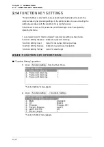
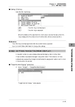
2.15.3
SETTING TARGET NUMBER DISPLAY
A target ID number is a value displayed beside the target symbol or AIS symbol.
These numbers are assigned to targets in acquisition order. The numbers 1 to 10 are
automatically assigned. Each target is identified by the assigned ID number until it is lost
or its acquisition is canceled.
"Target Number Display" operations
1
Open Target - Target Number Display .
"Target Number Display" menu appears.
Summary of Contents for JMA-3300 Series
Page 2: ......
Page 16: ...WARNING LABEL MOUNTING POINT xiv NCD 2182 Display Unit ...
Page 17: ...WARNING LABEL MOUNTING POINT xv NBA 5111 Power Supply NBD 865 Rectifier unit ...
Page 30: ...GLOSSARY xxviii ...
Page 46: ...Chapter 1 GENERAL AND EQUIPMENT COMPOSITION 1 5 GENERAL SYSTEM DIAGRAMS 1 16 ...
Page 244: ...Chapter 4 MAINTENANCE 4 6 TROUBLE SHOOTING 4 36 ...
Page 266: ...APPENDIX APPENDIX 2 Fig A2 NKE 2043 SCANNER INTERCONNECTION DIAGRAM ...
Page 268: ...APPENDIX APPENDIX 4 Fig A4 NKE 2062HS SCANNER INTERCONNECTION DIAGRAM ...
Page 271: ...APPENDIX APPENDIX 7 APPENDIX INSTRUCTION MANUAL LJ 1 6 6 11 5 17 5 211 7 21 5 0 ...
Page 272: ...APPENDIX APPENDIX 8 Fig A8 NKE 2063AHS SCANNER INTERCONNECTION DIAGRAM ...
Page 274: ...APPENDIX APPENDIX Fig A NCD 2182 DISPLAY UNIT INTERCONNECTION DIAGRAM ...
Page 276: ...APPENDIX APPENDIX 1 Fig A1 JMA 3314 INTERCONNECTION DIAGRAM ...
Page 277: ...APPENDIX APPENDIX 1 APPENDIX INSTRUCTION MANUAL Fig A1 JMA 3334 INTERCONNECTION DIAGRAM ...
Page 278: ...APPENDIX APPENDIX 1 Fig A1 JMA 3316 HS INTERCONNECTION DIAGRAM ...
Page 280: ...APPENDIX APPENDIX 1 Fig A1 JMA 3340 4 4HS 6 6HS INTERCONNECTION DIAGRAM ...
Page 297: ......