


Chapter 2
OPERATIONS
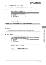
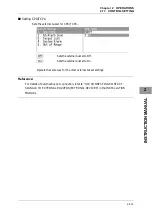
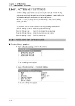
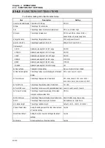
2.15
SETTING TT/AIS
2-120
2.15
SETTING TT/AIS
This section describes the operations of TT and AIS.
2.15.1
COLLISION AVOIDANCE
Problems of Collision Avoidance in Navigation
Marine collision avoidance is one of the problems that have been recognized from of old.
Now, it will be described briefly who the collision avoidance is positioned among the
navigational aid problems.
The navigation pattern of all mobile craft constitutes a system with some closed loops
regardless of the media through which the mobile craft travels, whether air, water, the
boundary between air and water, or space. This pattern consists of two closed loops in
principle, one of which is a collision with another mobile craft and the other is a loop of
finding a right and safe way to reach a predeterminate destination.
Fig. 2.15-1 shows the conceptual diagram of navigation pattern by MR. E.W. Anderson.
The closed loop of collision avoidance is shown on the left side and the closed loop of
finding a right course on the right side.
Fig. 2.15-1 Navigation Pattern
Destination
Mancuver
Cource and
speed
Course
Ship traveling in controlled condition
Insrument or
judgement
Control
loop
Compass
and log
Caluculati
on
Fixing by radio wave,
visual and celestial
observation
Judgement
Visual and radio
watch
Traffic rule
Cllision
avoidance loop
Vessel
̓
s Spacing loop
Collision avoidance
Decision of cource
Guide loop
Dead
reckoning
Summary of Contents for JMA-3300 Series
Page 2: ......
Page 16: ...WARNING LABEL MOUNTING POINT xiv NCD 2182 Display Unit ...
Page 17: ...WARNING LABEL MOUNTING POINT xv NBA 5111 Power Supply NBD 865 Rectifier unit ...
Page 30: ...GLOSSARY xxviii ...
Page 46: ...Chapter 1 GENERAL AND EQUIPMENT COMPOSITION 1 5 GENERAL SYSTEM DIAGRAMS 1 16 ...
Page 244: ...Chapter 4 MAINTENANCE 4 6 TROUBLE SHOOTING 4 36 ...
Page 266: ...APPENDIX APPENDIX 2 Fig A2 NKE 2043 SCANNER INTERCONNECTION DIAGRAM ...
Page 268: ...APPENDIX APPENDIX 4 Fig A4 NKE 2062HS SCANNER INTERCONNECTION DIAGRAM ...
Page 271: ...APPENDIX APPENDIX 7 APPENDIX INSTRUCTION MANUAL LJ 1 6 6 11 5 17 5 211 7 21 5 0 ...
Page 272: ...APPENDIX APPENDIX 8 Fig A8 NKE 2063AHS SCANNER INTERCONNECTION DIAGRAM ...
Page 274: ...APPENDIX APPENDIX Fig A NCD 2182 DISPLAY UNIT INTERCONNECTION DIAGRAM ...
Page 276: ...APPENDIX APPENDIX 1 Fig A1 JMA 3314 INTERCONNECTION DIAGRAM ...
Page 277: ...APPENDIX APPENDIX 1 APPENDIX INSTRUCTION MANUAL Fig A1 JMA 3334 INTERCONNECTION DIAGRAM ...
Page 278: ...APPENDIX APPENDIX 1 Fig A1 JMA 3316 HS INTERCONNECTION DIAGRAM ...
Page 280: ...APPENDIX APPENDIX 1 Fig A1 JMA 3340 4 4HS 6 6HS INTERCONNECTION DIAGRAM ...
Page 297: ......