


Chapter 2
OPERATIONS
2.14
FUNCTION KEY SETTINGS
2-116
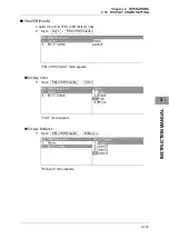
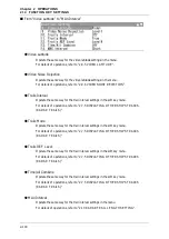
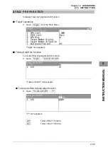
Bonden:
Use this mode when rain/snow clutter which cannot to be
suppressed is strong, such as a lot of floats of fixed net around the
ship.
Rain:
Use this mode when sea clutter is not strong but rain/snow clutter
is strong. (Importance is attached to rain/snow clutter suppression,
and sensitivity slightly lowers.)
US River:
Use this mode when adjusting the functions mainly suitable for
rivers in the United States.
Use this mode to reduce sea clutter returns (less effective than EU
river setting).
Long:
Use this mode to detect small targets at relatively long distance in
the open sea.
EU River:
Use this mode when adjusting the functions mainly suitable for
rivers in Europe.
Use this mode to reduce sea clutter returns.
User1:
General mode used when the nine modes above are not
applicable.
User2:
General mode used when the nine modes above are not
applicable.
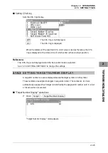
z
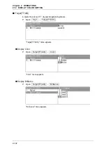
IR (Interference rejection)
Operate the same way for the interference rejection settings in the menu.
For details of operations, see Section "
Setting Radar Interference Rejection" of "2.9
RADAR ECHO SETTINGS".
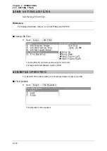
z
Process
Operate the same way for the process settings in the menu.
For details of operations, see Section "
Process" of "2.9 RADAR ECHO SETTINGS".
z
Target Enhance
Operate the same way for the target enhance settings in the menu.
For details of operations, see Section "
Setting for Enhancing Targets" of "2.9 RADAR
ECHO SETTINGS".
Summary of Contents for JMA-3300 Series
Page 2: ......
Page 16: ...WARNING LABEL MOUNTING POINT xiv NCD 2182 Display Unit ...
Page 17: ...WARNING LABEL MOUNTING POINT xv NBA 5111 Power Supply NBD 865 Rectifier unit ...
Page 30: ...GLOSSARY xxviii ...
Page 46: ...Chapter 1 GENERAL AND EQUIPMENT COMPOSITION 1 5 GENERAL SYSTEM DIAGRAMS 1 16 ...
Page 244: ...Chapter 4 MAINTENANCE 4 6 TROUBLE SHOOTING 4 36 ...
Page 266: ...APPENDIX APPENDIX 2 Fig A2 NKE 2043 SCANNER INTERCONNECTION DIAGRAM ...
Page 268: ...APPENDIX APPENDIX 4 Fig A4 NKE 2062HS SCANNER INTERCONNECTION DIAGRAM ...
Page 271: ...APPENDIX APPENDIX 7 APPENDIX INSTRUCTION MANUAL LJ 1 6 6 11 5 17 5 211 7 21 5 0 ...
Page 272: ...APPENDIX APPENDIX 8 Fig A8 NKE 2063AHS SCANNER INTERCONNECTION DIAGRAM ...
Page 274: ...APPENDIX APPENDIX Fig A NCD 2182 DISPLAY UNIT INTERCONNECTION DIAGRAM ...
Page 276: ...APPENDIX APPENDIX 1 Fig A1 JMA 3314 INTERCONNECTION DIAGRAM ...
Page 277: ...APPENDIX APPENDIX 1 APPENDIX INSTRUCTION MANUAL Fig A1 JMA 3334 INTERCONNECTION DIAGRAM ...
Page 278: ...APPENDIX APPENDIX 1 Fig A1 JMA 3316 HS INTERCONNECTION DIAGRAM ...
Page 280: ...APPENDIX APPENDIX 1 Fig A1 JMA 3340 4 4HS 6 6HS INTERCONNECTION DIAGRAM ...
Page 297: ......