


Chapter 2
OPERATIONS
2.14
FUNCTION KEY SETTINGS
2-115
2
INS
TRUCT
IO
N
M
ANUA
L
2.14.3
OVERVIEW OF FUNCTION SETTING ITEM
OPERATIONS
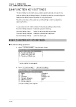
The following outlines the operation of each function selected from the function setting
menu.
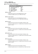
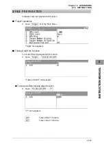
From "Function Enable/Disable" to "Pulse Length"
z
Function Enable/Disable
If "Function Enable/Disable" is set to "Off", this mode is not displayed when switching
operation mode of function key.
z
Mode
y
Selects the function name to be indicated at the lower left of the radar display when
the function is selected.
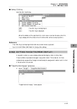
y
When the setting is changed back to the factory setting, the initial value of the
selected mode is called.
y
The following 12 modes are provided:
Standard:
Use this mode for general purpose. This is suitable to monitor a
relatively short range.
Coast:
Use this mode to monitor a relatively short range, for example,
bays and coasts where many boats and ships are running.
(Importance is attached to resolution.)
Deepsea:
Use this mode to monitor a relatively long range, for example, the
open sea.
(Importance is attached to long-range sensitivity.)
Fishnet:
Use this mode to detect small targets such as fishnets of round
haul netters hidden by sea clutter returns. (Importance is attached
to sea clutter suppression, and sensitivity to moving targets
lowers.)
Storm:
Use this mode when many rain/snow clutter returns or sea clutter
returns are detected in stormy weather. (Importance is attached to
rain/snow clutter and sea clutter suppression, and sensitivity
slightly lowers.)
Summary of Contents for JMA-3300 Series
Page 2: ......
Page 16: ...WARNING LABEL MOUNTING POINT xiv NCD 2182 Display Unit ...
Page 17: ...WARNING LABEL MOUNTING POINT xv NBA 5111 Power Supply NBD 865 Rectifier unit ...
Page 30: ...GLOSSARY xxviii ...
Page 46: ...Chapter 1 GENERAL AND EQUIPMENT COMPOSITION 1 5 GENERAL SYSTEM DIAGRAMS 1 16 ...
Page 244: ...Chapter 4 MAINTENANCE 4 6 TROUBLE SHOOTING 4 36 ...
Page 266: ...APPENDIX APPENDIX 2 Fig A2 NKE 2043 SCANNER INTERCONNECTION DIAGRAM ...
Page 268: ...APPENDIX APPENDIX 4 Fig A4 NKE 2062HS SCANNER INTERCONNECTION DIAGRAM ...
Page 271: ...APPENDIX APPENDIX 7 APPENDIX INSTRUCTION MANUAL LJ 1 6 6 11 5 17 5 211 7 21 5 0 ...
Page 272: ...APPENDIX APPENDIX 8 Fig A8 NKE 2063AHS SCANNER INTERCONNECTION DIAGRAM ...
Page 274: ...APPENDIX APPENDIX Fig A NCD 2182 DISPLAY UNIT INTERCONNECTION DIAGRAM ...
Page 276: ...APPENDIX APPENDIX 1 Fig A1 JMA 3314 INTERCONNECTION DIAGRAM ...
Page 277: ...APPENDIX APPENDIX 1 APPENDIX INSTRUCTION MANUAL Fig A1 JMA 3334 INTERCONNECTION DIAGRAM ...
Page 278: ...APPENDIX APPENDIX 1 Fig A1 JMA 3316 HS INTERCONNECTION DIAGRAM ...
Page 280: ...APPENDIX APPENDIX 1 Fig A1 JMA 3340 4 4HS 6 6HS INTERCONNECTION DIAGRAM ...
Page 297: ......