


Chapter 2
OPERATIONS
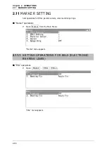
2.11
MARKER SETTING
2-90
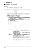
Setting bearing fix mode of parallel cursor
Reference:
y
Course data input is required for bearing fix mode setting.
y
True bearing signal input is required for N Up.
If this function is set to
Angle Fix
, the parallel cursor also rotates in accordance with
the bearing while the own ship is turning.
If the function is set to
Screen Fix
, the parallel index lines are fixed within the radar
display even while the own ship is turning. The parallel index lines are displayed at the
same place even while the own ship is turning.
1
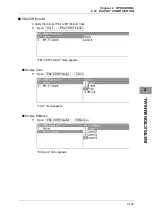
Open Parallel Cursor - Bearing Fix .
Angle Fix
:
The angle of the parallel cursors is set in true bearing.
For N Up and C Up, the cursors are displayed in true bearing
irrespective of changes in the course of own ship.
For H Up, the angle of the parallel cursors changes as the course
of own ship changes.
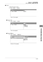
Screen Fix
:
Fixes the parallel cursor display to the radar display.
For H Up, N Up, and C Up, the angle of the parallel cursors stays
the same on the screen.
When own ship is engaged in TM motions, the parallel cursors
move as own ship moves.
Heading Fix
:
The parallel cursors are displayed while the relative angle of the
ship's heading bearing line stays the same.
For H Up, the ship's heading bearing line does not change even
though the course of own ship changes; therefore, the parallel
cursors do not move.
For N Up, the ship's heading bearing line changes as the course of
own ship changes; therefore, the parallel cursors also change as
the course of own ship changes.
Summary of Contents for JMA-3300 Series
Page 2: ......
Page 16: ...WARNING LABEL MOUNTING POINT xiv NCD 2182 Display Unit ...
Page 17: ...WARNING LABEL MOUNTING POINT xv NBA 5111 Power Supply NBD 865 Rectifier unit ...
Page 30: ...GLOSSARY xxviii ...
Page 46: ...Chapter 1 GENERAL AND EQUIPMENT COMPOSITION 1 5 GENERAL SYSTEM DIAGRAMS 1 16 ...
Page 244: ...Chapter 4 MAINTENANCE 4 6 TROUBLE SHOOTING 4 36 ...
Page 266: ...APPENDIX APPENDIX 2 Fig A2 NKE 2043 SCANNER INTERCONNECTION DIAGRAM ...
Page 268: ...APPENDIX APPENDIX 4 Fig A4 NKE 2062HS SCANNER INTERCONNECTION DIAGRAM ...
Page 271: ...APPENDIX APPENDIX 7 APPENDIX INSTRUCTION MANUAL LJ 1 6 6 11 5 17 5 211 7 21 5 0 ...
Page 272: ...APPENDIX APPENDIX 8 Fig A8 NKE 2063AHS SCANNER INTERCONNECTION DIAGRAM ...
Page 274: ...APPENDIX APPENDIX Fig A NCD 2182 DISPLAY UNIT INTERCONNECTION DIAGRAM ...
Page 276: ...APPENDIX APPENDIX 1 Fig A1 JMA 3314 INTERCONNECTION DIAGRAM ...
Page 277: ...APPENDIX APPENDIX 1 APPENDIX INSTRUCTION MANUAL Fig A1 JMA 3334 INTERCONNECTION DIAGRAM ...
Page 278: ...APPENDIX APPENDIX 1 Fig A1 JMA 3316 HS INTERCONNECTION DIAGRAM ...
Page 280: ...APPENDIX APPENDIX 1 Fig A1 JMA 3340 4 4HS 6 6HS INTERCONNECTION DIAGRAM ...
Page 297: ......