


Chapter 2
OPERATIONS
2.7
SOFT KEY OPERATION
2-73
2
INS
TRUCT
IO
N
M
ANUA
L
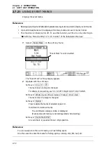
2.7.22
SETTING AIS FILTER
Once the AIS filter is set, only the AIS targets that are inside the filter area are displayed
(setting can be made such that AIS targets outside the AIS filter will not be shown).
The filter is initially set in a circle having a radius of 20 [NM] from the own ship's
position. If 50 or more targets exist in the filter range, they are displayed according to the
priority explained in "
AIS Symbols" of Section "2.7.6 AIS OPERATIONS".
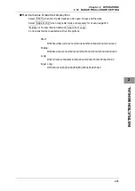
Reference:
y
Bearing signal input and latitude/longitude data input are required to use AIS functions.
y
This function is initially set to off. To use this function, set this to on by referring to
"
ڦ
Soft Key Menu Setting" in "4.10 Control" of the Installation Manual.
1
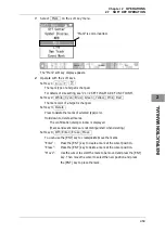
Select AIS Filter on the soft key menu.
The "AIS Filter" soft key display appears.
2
Operate with the soft keys.
Soft key 1:
Off Range
Switches between Off and Range..
"Range":
A filter is set in a circle with a set range as the radius.
Soft key 2:
Off On
"Off":
The filter is not displayed.
"On":
The filter is displayed.
"AIS Filter" is color-inverted.
Summary of Contents for JMA-3300 Series
Page 2: ......
Page 16: ...WARNING LABEL MOUNTING POINT xiv NCD 2182 Display Unit ...
Page 17: ...WARNING LABEL MOUNTING POINT xv NBA 5111 Power Supply NBD 865 Rectifier unit ...
Page 30: ...GLOSSARY xxviii ...
Page 46: ...Chapter 1 GENERAL AND EQUIPMENT COMPOSITION 1 5 GENERAL SYSTEM DIAGRAMS 1 16 ...
Page 244: ...Chapter 4 MAINTENANCE 4 6 TROUBLE SHOOTING 4 36 ...
Page 266: ...APPENDIX APPENDIX 2 Fig A2 NKE 2043 SCANNER INTERCONNECTION DIAGRAM ...
Page 268: ...APPENDIX APPENDIX 4 Fig A4 NKE 2062HS SCANNER INTERCONNECTION DIAGRAM ...
Page 271: ...APPENDIX APPENDIX 7 APPENDIX INSTRUCTION MANUAL LJ 1 6 6 11 5 17 5 211 7 21 5 0 ...
Page 272: ...APPENDIX APPENDIX 8 Fig A8 NKE 2063AHS SCANNER INTERCONNECTION DIAGRAM ...
Page 274: ...APPENDIX APPENDIX Fig A NCD 2182 DISPLAY UNIT INTERCONNECTION DIAGRAM ...
Page 276: ...APPENDIX APPENDIX 1 Fig A1 JMA 3314 INTERCONNECTION DIAGRAM ...
Page 277: ...APPENDIX APPENDIX 1 APPENDIX INSTRUCTION MANUAL Fig A1 JMA 3334 INTERCONNECTION DIAGRAM ...
Page 278: ...APPENDIX APPENDIX 1 Fig A1 JMA 3316 HS INTERCONNECTION DIAGRAM ...
Page 280: ...APPENDIX APPENDIX 1 Fig A1 JMA 3340 4 4HS 6 6HS INTERCONNECTION DIAGRAM ...
Page 297: ......