


Chapter 2
OPERATIONS
2.7
SOFT KEY OPERATION
2-69
2
INS
TRUCT
IO
N
M
ANUA
L
1
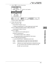
Select Mark on the soft key menu.
The "Mark" soft key display appears.
2
Operate with the soft keys.
Soft key 1:
X + Y
The mark type of a target is changed.
For details of size setting, see "2.17.2 SETTING MARK FUNCTIONS".
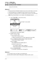
Soft key 2:
White Cyan Blue Green Yellow Pink Red
The mark color of a target is changed.
Soft key 3:
Delete
Press to delete the marks of selected type/color.
Hold down to delete all marks.
The confirmation dialog window is displayed.
(Marks and event marks are not distinguished when deleting.)
Soft key 4:
Off Enter Erase Move
You can use the
[ENT]
key to create/delete/move the marks.
"Enter":
Press the
[ENT]
key to create a mark at the cursor position.
"Erase":
Press the
[ENT]
key to delete a mark at the cursor position.
"Move":
Use the cursor to select the mark to be moved and press the
[ENT]
key. Then move the cursor to select the new position and press
the
[ENT]
key to place the mark.
"Mark" is color-inverted.
Summary of Contents for JMA-3300 Series
Page 2: ......
Page 16: ...WARNING LABEL MOUNTING POINT xiv NCD 2182 Display Unit ...
Page 17: ...WARNING LABEL MOUNTING POINT xv NBA 5111 Power Supply NBD 865 Rectifier unit ...
Page 30: ...GLOSSARY xxviii ...
Page 46: ...Chapter 1 GENERAL AND EQUIPMENT COMPOSITION 1 5 GENERAL SYSTEM DIAGRAMS 1 16 ...
Page 244: ...Chapter 4 MAINTENANCE 4 6 TROUBLE SHOOTING 4 36 ...
Page 266: ...APPENDIX APPENDIX 2 Fig A2 NKE 2043 SCANNER INTERCONNECTION DIAGRAM ...
Page 268: ...APPENDIX APPENDIX 4 Fig A4 NKE 2062HS SCANNER INTERCONNECTION DIAGRAM ...
Page 271: ...APPENDIX APPENDIX 7 APPENDIX INSTRUCTION MANUAL LJ 1 6 6 11 5 17 5 211 7 21 5 0 ...
Page 272: ...APPENDIX APPENDIX 8 Fig A8 NKE 2063AHS SCANNER INTERCONNECTION DIAGRAM ...
Page 274: ...APPENDIX APPENDIX Fig A NCD 2182 DISPLAY UNIT INTERCONNECTION DIAGRAM ...
Page 276: ...APPENDIX APPENDIX 1 Fig A1 JMA 3314 INTERCONNECTION DIAGRAM ...
Page 277: ...APPENDIX APPENDIX 1 APPENDIX INSTRUCTION MANUAL Fig A1 JMA 3334 INTERCONNECTION DIAGRAM ...
Page 278: ...APPENDIX APPENDIX 1 Fig A1 JMA 3316 HS INTERCONNECTION DIAGRAM ...
Page 280: ...APPENDIX APPENDIX 1 Fig A1 JMA 3340 4 4HS 6 6HS INTERCONNECTION DIAGRAM ...
Page 297: ......