


Chapter 2
OPERATIONS
2.7
SOFT KEY OPERATION
2-55
2
INS
TRUCT
IO
N
M
ANUA
L
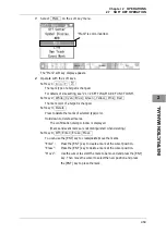
Soft key 2:
Manual Tuning
When pressing the soft key 2, "Manual Tuning" is color-inverted.
y
When "MAN" is displayed above the soft key 1
You can manually adjust using the MULTI control.
Turn the MULTI control to adjust tuning.
Adjust the video to be the largest by observing the tune indicator bar.
Because the tune indicator bar is the guide during manual tuning, adjust the
tune indicator bar to the maximum.
y
When "AUTO" is displayed above the soft key 1
"Manual Tuning" is not color-inverted. The equipment automatically adjust
tuning. Tuning is adjusted when transmission is started, the range is changed
or pulse length is changed.
Soft key 3:
PRF Fine Tuning
When pressing the soft key 3, "PRF Fine Tuning" is color-inverted.
The PRF fine tuning screen appears.
Fine-tune the transmitting repetition frequency of the transmitter in the range 90
to 100%.
If radar's interference patterns are concentrically displayed, increment or
decrement the set value by 3 to 4 in order to heighten the effect of interference
rejection.
The same operation can be performed by pressing the
[TX/PRF]
key several
times.
Use the
[MULTI]
control to perform PRF fine tuning between 0 and 31.
When the soft key 3 "PRF Fine Tuning" is pressed, color-inverted display returns
to normal color.
Soft key 4: Not available
Tune indicator bar
Summary of Contents for JMA-3300 Series
Page 2: ......
Page 16: ...WARNING LABEL MOUNTING POINT xiv NCD 2182 Display Unit ...
Page 17: ...WARNING LABEL MOUNTING POINT xv NBA 5111 Power Supply NBD 865 Rectifier unit ...
Page 30: ...GLOSSARY xxviii ...
Page 46: ...Chapter 1 GENERAL AND EQUIPMENT COMPOSITION 1 5 GENERAL SYSTEM DIAGRAMS 1 16 ...
Page 244: ...Chapter 4 MAINTENANCE 4 6 TROUBLE SHOOTING 4 36 ...
Page 266: ...APPENDIX APPENDIX 2 Fig A2 NKE 2043 SCANNER INTERCONNECTION DIAGRAM ...
Page 268: ...APPENDIX APPENDIX 4 Fig A4 NKE 2062HS SCANNER INTERCONNECTION DIAGRAM ...
Page 271: ...APPENDIX APPENDIX 7 APPENDIX INSTRUCTION MANUAL LJ 1 6 6 11 5 17 5 211 7 21 5 0 ...
Page 272: ...APPENDIX APPENDIX 8 Fig A8 NKE 2063AHS SCANNER INTERCONNECTION DIAGRAM ...
Page 274: ...APPENDIX APPENDIX Fig A NCD 2182 DISPLAY UNIT INTERCONNECTION DIAGRAM ...
Page 276: ...APPENDIX APPENDIX 1 Fig A1 JMA 3314 INTERCONNECTION DIAGRAM ...
Page 277: ...APPENDIX APPENDIX 1 APPENDIX INSTRUCTION MANUAL Fig A1 JMA 3334 INTERCONNECTION DIAGRAM ...
Page 278: ...APPENDIX APPENDIX 1 Fig A1 JMA 3316 HS INTERCONNECTION DIAGRAM ...
Page 280: ...APPENDIX APPENDIX 1 Fig A1 JMA 3340 4 4HS 6 6HS INTERCONNECTION DIAGRAM ...
Page 297: ......