


Chapter 2
OPERATIONS
2.7
SOFT KEY OPERATION
2-54
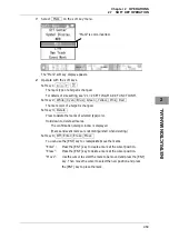
Soft key 2:
Monitor BRILL
When "Brilliance" of the soft key menu is selected, "Monitor BRILL" of the soft
key display is color-inverted.
Press the
[BRILL]
key to adjust at eight levels.
Also, you can turn the
[MULTI]
control to change the level.
Soft key 3: Not available
Soft key 4: Not available
Reference:
When "Brilliance" is not selected on the soft key menu, press the soft key 4 to activate the
Brilliance function.
2.7.10
ADJUSTING SCANNER
There are automatic tuning mode (AUTO) and manual tuning mode (MAN). In the
automatic tuning mode, transmission and receiving frequencies are tuned and adjusted
automatically. In the manual tuning mode, tuning is carried out using the MULTI
control.
1
Select TUNE/PRF on the soft key menu.
The "TUNE/PRF" soft key display appears.
2
Operate with the soft keys.
Soft key 1:
AUTO Tune Manual Tune
Selects whether to use the tuning function in automatic or manual mode.
"TUNE/PRF" is color-inverted.
Summary of Contents for JMA-3300 Series
Page 2: ......
Page 16: ...WARNING LABEL MOUNTING POINT xiv NCD 2182 Display Unit ...
Page 17: ...WARNING LABEL MOUNTING POINT xv NBA 5111 Power Supply NBD 865 Rectifier unit ...
Page 30: ...GLOSSARY xxviii ...
Page 46: ...Chapter 1 GENERAL AND EQUIPMENT COMPOSITION 1 5 GENERAL SYSTEM DIAGRAMS 1 16 ...
Page 244: ...Chapter 4 MAINTENANCE 4 6 TROUBLE SHOOTING 4 36 ...
Page 266: ...APPENDIX APPENDIX 2 Fig A2 NKE 2043 SCANNER INTERCONNECTION DIAGRAM ...
Page 268: ...APPENDIX APPENDIX 4 Fig A4 NKE 2062HS SCANNER INTERCONNECTION DIAGRAM ...
Page 271: ...APPENDIX APPENDIX 7 APPENDIX INSTRUCTION MANUAL LJ 1 6 6 11 5 17 5 211 7 21 5 0 ...
Page 272: ...APPENDIX APPENDIX 8 Fig A8 NKE 2063AHS SCANNER INTERCONNECTION DIAGRAM ...
Page 274: ...APPENDIX APPENDIX Fig A NCD 2182 DISPLAY UNIT INTERCONNECTION DIAGRAM ...
Page 276: ...APPENDIX APPENDIX 1 Fig A1 JMA 3314 INTERCONNECTION DIAGRAM ...
Page 277: ...APPENDIX APPENDIX 1 APPENDIX INSTRUCTION MANUAL Fig A1 JMA 3334 INTERCONNECTION DIAGRAM ...
Page 278: ...APPENDIX APPENDIX 1 Fig A1 JMA 3316 HS INTERCONNECTION DIAGRAM ...
Page 280: ...APPENDIX APPENDIX 1 Fig A1 JMA 3340 4 4HS 6 6HS INTERCONNECTION DIAGRAM ...
Page 297: ......