background image

4

Operation

4.2

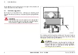
Mounting and locking the container

1

2

3

TL403/004

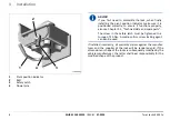
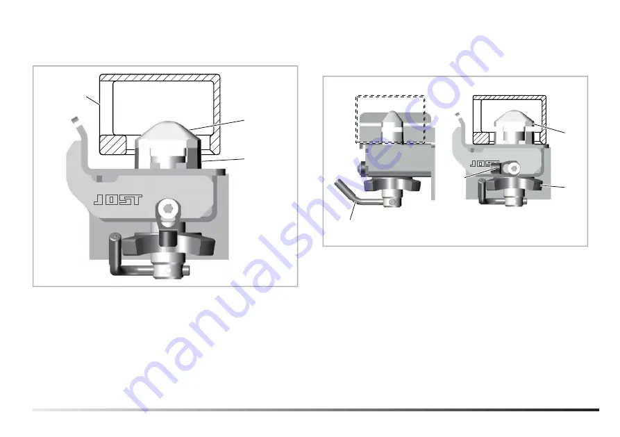
1

Corner fitting of container

2

Pivot head

3

Guide bush

Before putting on the container, make sure the locks are in the

correct position for mounting.
For this, the pivot head and guide bush must be facing the same

way, as shown in Fig. TL403/004.
The container can now be mounted.

Its corner fittings must not show any inadmissible deformations or

inadmissible wear.

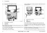
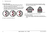
4

6

5

7

TL403/005

4

Pivot position indicator

5

Pivot

6

Safety catch

7

Clamping nut

After loading, the corner fitting must lie flush against the lock.
As shown on the left in Fig. TL403/004, the pivot position indica-

tor projects over the side of the housing when the container is

unlocked.
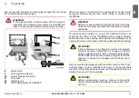
Next, open the safety catch. To do so, push the catch up, turn it 90°

and, with it now horizontal, pull it sideways.
The clamping nut can now be rotated; first slacken it a few turns.

10

MUB 013 005 M30


(REV-B)


07-2020

Twist Locks R 403 Fx

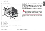
Summary of Contents for R 403 FL

Page 1: ...Twist Locks R 403 FR R 403 FL EN Installation and operating instructions Twist Locks R 403 FR R 403 FL EN Installation and operating instructions ...

Page 2: ...2 MUB 013 005 M30 REV B 07 2020 Twist Locks R 403 Fx ...
Page 3: ... Installation 6 3 1 Installation suggestions 6 4 Operation 9 4 1 Operating equipment 9 4 2 Mounting and locking the container 10 4 3 Tipping process 12 4 4 Unlocking the container 12 5 Maintenance 13 5 1 Inspection instructions 13 5 2 Disposal instructions 15 EN Twist Locks R 403 Fx MUB 013 005 M30 REV B 07 2020 3 ...

Page 4: ...damage can occur if the relevant safety instruc tions are not followed ATTENTION Means that slight physical injury or material damage can occur if the relevant safety instructions are not fol lowed ADVICE Contains additional important information 4 MUB 013 005 M30 REV B 07 2020 Twist Locks R 403 Fx ...

Page 5: ...ction of travel the R 403 FR on the right The lock components are reinforced so that they can absorb the loads acting on the tipping chassis during tipping The admissible loads can be found in the technical data see Chapter 2 2 Technical data and spare parts We recommend fitting additional rear stabilisers for use during the tipping process 2 2 Technical data and spare parts ADVICE Test report 810...

Page 6: ...nt from one another lead to a high risk of accident when the container is tipped and must be avoided 1 max 80 TL403 001 The rotating axle 1 should be positioned at the same height as the pivot in the direction of travel and no more than 80 mm below the support surface see Fig TL403 001 ATTENTION Exceeding this distance or positioning the rotating axle further forward in the direction of travel con...

Page 7: ...onnel The relevant currently valid standards and codes of practice must be observed See the following table for approved filler metals and welding con sumables Approved filler metals Welding process EII MAG C MAG M Filler metal Electrode rod Welding wire Name of stan dard ISO 2560 A E 35 0 A5 ISO 14341 A G 42 0 M C G3Si1 ISO 14341 A G 42 0 M C G4Si1 Approved welding consumables Welding process EII...

Page 8: ...hnical data and spare parts The screw in the safety latch must be tightened to a torque of 25 Nm A medium firm screw locking agent can also be used If installed incorrectly all warranty claims against the manufac turer and the supplier of the lock will be rendered void If the dimensions or shape of the lock are subsequently modified by the vehicle manufacturer the latter shall bear responsibility ...

Page 9: ...security to prevent the container from slipping when used as intended it does not absorb any forces A gap must be visible between the thrust plate and the corner fit ting of the container WARNING If the corner fitting is lying against the thrust plate dur ing tipping inspect the lock immediately for compli ance with the criteria set out in Chapter 5 1 Inspection instructions A faulty corner fittin...

Page 10: ...t show any inadmissible deformations or inadmissible wear 4 6 5 7 TL403 005 4 Pivot position indicator 5 Pivot 6 Safety catch 7 Clamping nut After loading the corner fitting must lie flush against the lock As shown on the left in Fig TL403 004 the pivot position indica tor projects over the side of the housing when the container is unlocked Next open the safety catch To do so push the catch up tur...

Page 11: ...r is now in the direction of travel as shown on the left in of Fig TL403 006 and no longer projects above the side of the housing Next tighten the clamping nut by hand until it comes into contact with the underside of the housing ATTENTION If the container is to be tipped as well as transported normally on roads tighten the nut to approx 100 Nm using a suitable tool e g JOST universal operating ke...

Page 12: ...n the danger zone during the tipping process and make sure that other persons also stay out of this area 4 4 Unlocking the container The basic procedure for unlocking and lifting off the container is the reverse of that described in Chapter 4 2 Mounting and locking the container Bring the safety catch into a horizontal position so that you can then slacken the clamping nut Using a suitable tool su...

Page 13: ...y before driving commences At least every six weeks have the following tests performed by a qualified specialist Housing Function test of internal lock parts all operating positions described in the instructions for use can be reached Check housing for abnormal deformation minor deformation due to operation e g of the upper panel is admissible Check guide bush for deformations that adversely affec...

Page 14: ...formation The check should preferably be performed with the components removed JSMTL 012 Examples of inadmissible thread wear Check the pivot head especially the underside for visible abnormal local wear abnormal deformations and damage that adversely affects function JSMTL 013 Examples of inadmissible wear on the pivot head Pivot position indicator Check that the indicator itself and the two dowe...

Page 15: ...5 2 Disposal instructions The installed parts are valuable raw materials that can be recycled Before disposal clean parts to remove any residual oil or grease EN Twist Locks R 403 Fx MUB 013 005 M30 REV B 07 2020 15 ...

Page 16: ...Member of JOST World JOST Germany Tel 49 6102 295 0 tkd technik jost world com www jost world com MUB 013 005 M30 REV B 07 2020 2 2 ...

Reviews: