background image

22

KEY

PART

NO.

NO.

DESCRIPTION

NOTE:

  All component dimensions given in U.S. inches.

 1 inch = 25.4 mm

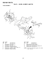
1

532 18 06-77

Transmission Assembly
(Includes Key Nos. 2-53)

2

532 18 06-27

Gearcase, L.H. w/Bearing
(Includes Key No. 4)

3

532 16 19-63 Gasket, Gearcase

4

532 00 50-20 Bearing, Needle

5

532 00 13-70 Washer, Thrust  5/8 x 1.10 x 1/32

6

532 13 73-35 Pinion, Input

7

532 14 51-01 Shaft,  Input

8

532 12 47-92 Bearing, Needle

9

532 15 44-67 Washer, Seal

10

532 12 46-97 Ball,  Steel

11

532 10 03-71 Spring,  Shift,  Fork

12

532 10 61-60 O-Ring

13

532 14 21-45 Arm,  Shift

14

532 00 83-53 Fork,  Shift

15

812 00 00-39 Ring, Klip

16

532 15 44-66 Shaft,  Shift

18

532 00 43-58 Washer

19

812 00 00-40 Ring, Klip

20

532 10 21-14 Gear, Assembly, Reverse Idler

(Includes Key Nos. 21 and 22)

21

532 10 21-15 Gear, Reverse Idler

22

532 00 68-03 Bearing, Needle

23

532 10 21-11 Shaft, Reverse Idler

REPAIR PARTS

TILLER - - MODEL NUMBER JNART5B

TRANSMISSION

KEY

PART

NO.

NO.

DESCRIPTION

24

810 04 07-00 Washer, Lock  7/16

25

873 61 07-00 Nut, Hex  7/16-20

27

532 14 30-09 Bearing, Shaft, Ground Drive L.H.

28

532 10 63-90 Spacer  0.765 x 1.125 x 1.23

29

532 10 21-34 Chain  #35-50 Pitch

30

532 15 07-37 Ground Shaft Assembly

31

532 14 30-08 Bearing, Shaft, Ground Drive R.H.

32

532 10 63-88 Spacer  0.70 x 1.00 x 1.150

33

532 10 21-21 Sprocket and Gear Assembly

34

532 10 21-12 Shaft, Reduction (2nd)

35

532 10 21-01 Screw, Whiz, Lock  5/16-18 x 3-1/2

36

532 15 43-55 Sprocket Assembly w/Bearing

(Includes Key Nos. 37 and 38)

37

532 12 47-91 Bearing, Needle

38

532 15 43-56 Sprocket, Tine

39

532 10 53-45 Gear, Cluster, Red 1st & 2nd

40

532 10 53-46 Gear, Reverse

41

532 00 83-58 Shaft, Reduction (1st)

42

532 00 42-20 Washer, Thrust

43

532 10 61-46 Spacer  1.01 x 1.75 x 0.760

44

532 15 52-36 Seal  Asm,  Oil

48

532 18 06-31

Gearcase, R.H. w/Bearing
(Includes Key No. 8)

49

532 13 26-88 Shaft,  Tine

50

532 10 61-47 Chain, Roller  #50-50 Pitch

51

817 72 04-08 Screw  1/4-20 x 1/2

52

873 22 05-00 Nut, Hex  5/16-18

53

532 16 51-40 Kit, Bearing

58

532 17 95-20

Bolt Shoulder

60

532 12 48-36 Fitting Grease

- -

532 00 60-66 Grease, Plastilube #1

Summary of Contents for JNART5B

Page 1: ...532 18 25 44 2 19 02 TR PRINTED IN U S A Assembly Operation Customer Responsibilities Service and Adjustments Storage Troubleshooting Repair Parts OWNER S MANUAL MODEL NO JNART5B 5 HP 17 Inch Tiller...

Page 2: ...toptheunitanddisengagethe controls quickly Never allow children to operate the equipment Never allow adults to operate the equipment without proper instruction Keep the area of operation clear of all...

Page 3: ...COMBUSTION ENGINE AND SHOULD NOT BE USED ON OR NEAR ANY UNIMPROVED FOREST COVERED BRUSH COVERED OR GRASS COVERED LAND UNLESS THE ENGINE S EXHAUST SYSTEM IS EQUIPPED WITH A SPARK ARRESTER MEETING APPLI...

Page 4: ...has been assembled at the factory with exception of those parts left unassembled for shipping purposes To ensuresafeandproperoperationofyourtillerallpartsandhardwareyouassemblemustbetightenedsecurely...

Page 5: ...assembly is lowered into position HANDLE ASSEMBLY FIG 3 HANDLE ASSEMBLY GEARCASE NOTCH HANDLE LOCK VIEWED FROM R H SIDE OF TILLER LOOSEN HANDLE LOCK LEVER TO MOVE TIGHTEN HANDLE LOCK LEVER TO HOLD CAR...

Page 6: ...gh hole of shift rod to secure FIG 7 FIG 6 END OF CLUTCH CABLE CONTROL BAR CONTROL BAR BRACKET CONTROL BAR BRACKET CLUTCH CABLE ATTACH CLUTCH CABLE See Fig 6 Hook end of clutch cable through hole in c...

Page 7: ...DLE SHIFT LEVER INDICATOR THROTTLE CONTROL OUTER SIDE SHIELD FIG 8 MEETS ANSI SAFETY REQUIREMENTS Our tillers conform to the safety standards of the American National Standards Institute CHOKE CONTROL...

Page 8: ...tion and engaging drive control bar FORWARD WHEELS ONLY TINES STOPPED Release drive control bar and move shift lever indicator to F forward position Engage drive control bar and tiller will move forwa...

Page 9: ...ed gasohol or using ethanol or methanol can attract moisture which leads to separation and formation of acids during storage Acidic gas can damage the fuel system of anenginewhileinstorage Toavoidengi...

Page 10: ...ainfallandwind itmay be advisable to till the soil at the end of the growing season to further condition the soil Youwillfindtillingmucheasierifyouleavearowuntilled between passes Then go back between...

Page 11: ...Check tine operation Check for loose fasteners LUBRICATION Keep unit well lubricated See LUBRICATION CHART SAE 30 OR 10W 30 MOTOR OIL REFER TO CUSTOMER RESPONSIBILITIES ENGINE SECTION EP 1 GREASE LUBR...

Page 12: ...at least once a year if the tiller is not used for 25 hours in one year Checkthecrankcaseoillevelbeforestartingtheengineand after each five 5 hours of continuous use Add SAE 30 motor oil or equivalen...

Page 13: ...finished surfaces and wheels free of all gasoline oil etc Protect painted surfaces with automotive type wax SERVICE AND ADJUSTMENTS CAUTION Disconnect spark plug wire from spark plug and place wire w...

Page 14: ...GROUND DRIVE BELT See Fig 23 Removebeltguard See TOREMOVEBELTGUARD in this section of this manual Remove old belt by slipping off engine pulley first then remove from transmission pulley Placenew belt...

Page 15: ...maintain the superb tilling performance of this ma chine the tines should be checked for sharpness wear and bending particularly the tines which are next to the transmission If the gap between the ti...

Page 16: ...p until it touches high speed stop and hold in this position Tighten cable clamp screw securely TO ADJUST CARBURETOR The carburetor has been preset at the factory and adjust ment should not be necessa...

Page 17: ...Drain the fuel tank Start the engine and let it run until the fuel lines and carburetorareempty Never use engine or carburetor cleaner products in the fuel tank or permanent damage may occur Use fres...

Page 18: ...d clean carburetor 6 Stale or dirty fuel 6 Drain fuel tank and refill with fresh gasoline 7 Water in fuel 7 Drain fuel tank and carburetor and refill tank with fresh gasoline 8 Clogged fuel tank 8 Rem...

Page 19: ...7 44 Clamp Bar Control KEY PART NO NO DESCRIPTION 1 5321806 34 Control Throttle 2 5320092 66 Grip Handle 4 5321592 28 Bar Assembly Control 6 5321806 78 Panel Control 8 8711910 08 Screw Truss Hd 10 24...

Page 20: ...5 16 24 UNF x 1 2 23 5320050 15 Tire 5321243 66 Rim 5321247 18 Tire Valve 24 5321268 75 Rivet Drilled 25 5321247 88 Clip Hairpin 26 5321674 88 Guard Belt 27 5321328 01 Belt V 28 5321046 79 Pulley Idle...

Page 21: ...cement 6 8747605 32 Bolt Hex 5 16 18 x 2 7 5321021 73 CounterWeight R H 8 8100406 00 Washer Lock 3 8 9 8732206 00 Nut Hex 3 8 16 10 8747605 24 Bolt Hex 5 16 18 x 1 1 2 11 5321247 88 Clip Hairpin NOTE...

Page 22: ...RT NO NO DESCRIPTION 24 8100407 00 Washer Lock 7 16 25 8736107 00 Nut Hex 7 16 20 27 5321430 09 Bearing Shaft Ground Drive L H 28 5321063 90 Spacer 0 765 x 1 125 x 1 23 29 5321021 34 Chain 35 50 Pitch...

Page 23: ...Nut Lock Hex Flange 5 16 18 2 5321640 62 Shield Side Outer L H 3 5320083 93 Pin Stake Depth 4 8120000 35 Ring Klip 5 8721405 06 Bolt Carriage 5 16 18 x 3 4 Gr 5 6 5320083 94 Spring 7 5320083 92 Bracke...

Page 24: ...Spring Zinc 5 5321327 27 Assembly Hub and Plate L H 6 8736106 00 Nut Hex 3 8 24 7 8100406 00 Washer Lock 3 8 8 8746106 16 Bolt Hex 3 8 24 x 1 9 5320044 60 Tine Outer R H 10 5321327 28 Assembly Hub and...

Page 25: ...Indicator 7 5321623 84 Decal Warning 8 5321756 43 Decal Engine B S 9 5321200 76 Decal Warning Rotating Tines 10 5321710 77 Decal Engine OHV N I C 11 5321710 78 Decal Rewind Intek 274350 5321825 44 Ma...

Page 26: ...26 SERVICENOTES...

Page 27: ...27 SERVICENOTES...

Page 28: ......

Reviews: