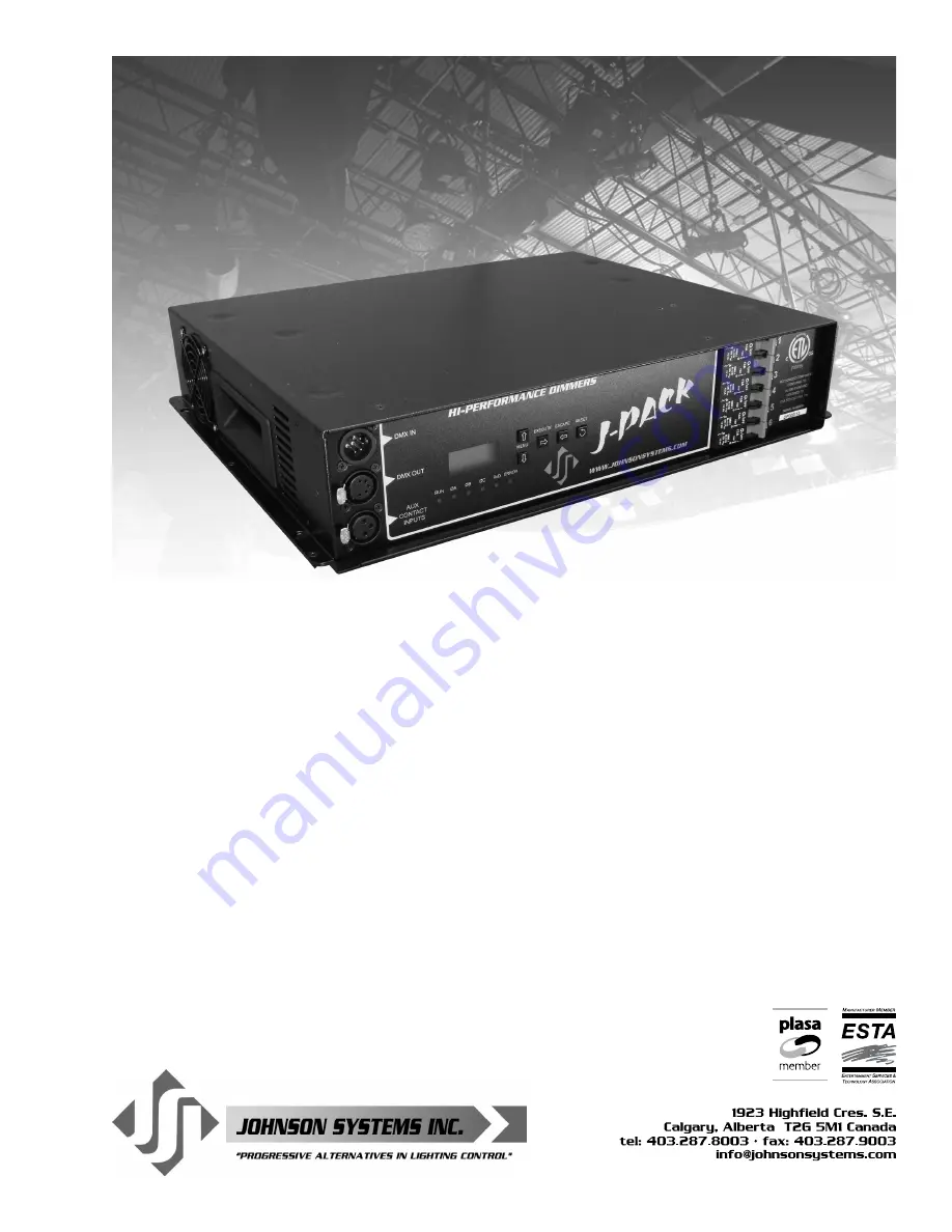
User Manual
J-PACK Series
Hi-Performance Dimmer Pack
JOHNSON SYSTEMS INC.
WWW.JOHNSONSYSTEMS.COM
Page 1: ...User Manual J PACK Series Hi Performance Dimmer Pack JOHNSON SYSTEMS INC WWW JOHNSONSYSTEMS COM ...
Page 2: ... you with the necessary information please contact our factory via email info johnsonsystems com or phone 403 287 8003 during business hours Monday to Friday 8 00AM to 5 00PM MST Contents Warranty 2 Introduction 3 Characteristics 4 Installation 6 Mounting Options 6 AC Power Supply Input Options 8 Output Connector Receptacle Options 10 Output Connector Receptacle Diagrams 12 Control Input 12 MADD 6...
Page 3: ...nputs and contact closure inputs allow for industry wide application On demand MagLev thermal management technology produces superior cooling that is virtually silent making J PACK s the natural choice for quiet space dimming installations Exclusive lamp warming techniques extends lamp life considerably while maintaining industry leading performance Features Available in a range of voltage and out...
Page 4: ...re Max Rating 9 000W Power Termination Power lug input Output selection of Terminal Block Stage Pin Edison TLG or Socapex Maximum output 1 560 Watts per circuit Environment Temperature Range 23 F 5 C to 104 F 40 C ambient Humidity Range 0 to 90 non condensing Load Type Incandescent quartz lamps and electronic SCR dimmable low voltage fixtures Switch Type 300 rated non proprietary SCR solid state r...
Page 5: ...haust Air Intake Ten 10 SEMS 6 32 x 3 8 Philips Pan Head Top Panel Lid Mounting Screws Six 6 6 32 x 3 8 Philips Flat Head Top Panel Lid Mounting Screws Four 4 SEMS 6 32 x 3 8 Philips Pan Head Rack Mount Bracket Mounting Screws Four 4 Safety Cable Mounting Holes For PM model only Six 6 Indents For vertical stacking Safety Cable supplied on PM model ...
Page 6: ...r packs are capable of various mounting options to suit the application required A cooling fan mounted inside the dimmer pack is used to move air through the chassis and cool the heat sink and chokes The fan is temperature controlled via a temperature sensor mounted on the heat sink If the heat sink temperature is 55ºC the fan is turned on to half speed If the heat sink temperature is 70ºC the fan...
Page 7: ...lts are required to fasten and secure the rack safely to the wall WARNING Never mount the dimmer packs side by side vertically without a minimum of 12 of clearance between them Always leave a minimum of 6 of clearance from the dimmer packs air intake and exhaust Failure to comply may cause thermal overheating RM Rack Mount For rack mounting brackets are provided and used to secure the dimmer pack ...
Page 8: ...he conduit to the rear panel Only use wire rated for the specifications provided Route the wire directly from the conduit entry into the power terminals Use a 3 16 flathead screwdriver to torque the power terminals to the specifications provided Once the AC power supply input wiring termination is complete carefully reinstall the top panel lid If the cooling fan cable was disconnected be sure to r...
Page 9: ...6 are powered from a single power cord Available only with Duplex Edison NEMA 5 15 output connectors receptacles 120 240 120 240VAC 1Ø 4 Wire Terminal Block Up to 40 Amps per phase maximum 9 000W total Use wire size 12 to 4 AWG copper wire only rated for 167 F 75 C minimum Strip insulation length to 0 44 11mm Torque power terminals A B N to 10 5 IN LBS 1 2 NM Dimmers 1 3 and 5 are powered from Pha...
Page 10: ...ies dimmer packs supplied with factory installed dual 2 Edison power cords are capable of dimming a total of 3 600 Watts shared between the six 6 Duplex Edison output receptacles 120VAC Output Receptacle with Factory Installed Single or Dual Edison Power Cord ED 15A Duplex Edison NEMA 5 15 120VAC Operation Capable of dimming six 6 1 560 Watt dimmer output circuits fully protected by premium 13 Amp...
Page 11: ... into the output load terminals Use a 3 16 flathead screwdriver to torque the power terminals to the specifications provided below Each dimmer output load circuit 120VAC 1Ø 3 Wire requires three 3 conductors one 1 for hot one 1 for neutral and one 1 for ground There are six 6 hot terminals six 6 neutral terminals and six 6 ground terminals one for each dimmer output connection Once the dimmer outp...
Page 12: ...connects to the 5 pin XLR connectors located on the front panel DMX alternatively connects to the internal 3 pin breakaway type connectors Complies with USITT DMX512 A ANSI E1 11 2008 Standard protocol for digital data control Recommended cable is Belden 9829 9842 Cat 5 or equivalent low capacitance twisted pair Wiring must follow a daisy chain topology Maximum of 32 receiving devices on a single ...
Page 13: ...t The auxiliary inputs are used to activate a selected scene or for load shed applications The auxiliary inputs may be interfaced with compatible AV control equipment photocells occupancy sensors and building management systems BMS A third auxiliary input AUX3 is located internally and is for future use Refer to menu items AUX TEST AUX1MODE AUX2MODE and LOADSHED on pages 23 24 for further details ...
Page 14: ...can be helpful to speed up the configuration time The EXECUTE switch is normally used to select enter a menu item advance forward within a selected menu item or toggle between parameters within a selected menu item The ESCAPE switch is normally used to back up within a selected menu item one step at a time or exit the menu completely The RESET switch has two purposes First it allows for quick exit...
Page 15: ...LCD Display When DMX is being received the top line of the LCD display shows the DMX start address DMX 001 to DMX 512 unless the system is in DMX patch mode then DMX PAT is displayed When DMX is not being received the top line of the LCD display shows MADD 6 unless the system is in standby mode then STANDBY is displayed The bottom line of the LCD display shows the current status of the system unle...
Page 16: ...mer outputs are disabled and the fans are turned on to full until the temperature cools down to 178 F 81 C or less Refer to menu item CTL TEMP on page 26 to view the microcontroller temperature Ø ERROR Displayed when an error is sensed on any of the input power phases A phase error can be caused from an under voltage of less than 100VAC for 120VAC operation and 200VAC for 240VAC operation an over ...
Page 17: ...s to percent or hexadecimal 17 SCENEMOD Enable or disable scene mode 18 AUX TEST Test the auxiliary dry contact inputs 19 AUX1MODE Set the auxiliary input 1 mode to activate a selected scene or load shed 20 AUX2MODE Set the auxiliary input 2 mode to activate a selected scene or load shed 21 LOADSHED Select dimmers to be disabled turned off by the auxiliary inputs 22 Ø PATCH Set the zero cross phas...
Page 18: ...art address can be assigned from 001 to 512 Press EXECUTE to enter the menu DMX 001 Displays the current DMX start address for both DMX inputs DMX 512 Press MENU to modify and select the desired DMX start address DMX 001 Press both MENU simultaneously to toggle to DMX start address 001 Press ESCAPE to exit the menu and save the selected DMX start address Press RESET to exit the menu without saving...
Page 19: ...channel C and level L C 06L 00 Press MENU to select the control channel C to modify from 01 to 06 C 06L 00 Press EXECUTE to toggle from channel C to level L selection C 06L 00 Press ESCAPE to toggle from level L to channel C selection C 06L FF Press MENU to select the output level L for the selected channel from 00 to FF CLEAR Press EXECUTE to clear the selected preset and set all channels to 00 l...
Page 20: ...vel is displayed as a 9 bit value from 000 to 512 This menu does not timeout automatically and will continue to monitor indefinitely Press EXECUTE to enter the menu and activate monitor mode D 01L000 Press MENU to select the dimmer D output to monitor from 01 to 06 D 06L512 Display shows dimmer 06 has full on control Press ESCAPE or RESET to exit the menu NOTE The control level value will not reac...
Page 21: ...When DMX is disconnected the system will hold the status of the last received DMX levels for the selected amount of time When activated the LCD display shows a countdown of the status hold time or infinite hold Press EXECUTE to enter the menu HTIME 00 Displays the current DMX status hold time HTIME setting HTIME 99 Press MENU to set the desired hold time from 00 to 99 minutes HTIME XX Press MENU t...
Page 22: ...ired dimmer number from 01 to 06 06 127 5 Press EXECUTE to toggle the pointer to select the output voltage level 06 100 0 Press MENU to adjust the output voltage level in 0 5 Volt increments 06 100 0 Press EXECUTE to toggle the pointer to select another dimmer number Press ESCAPE to exit the menu and save the desired dimmer curves Press RESET to exit the menu without saving The menu will automatic...
Page 23: ...nd the auxiliary input When there is a connection between common and the auxiliary input the auxiliary input is activated Press EXECUTE to enter the menu 1 2 Displays auxiliary input 1 1 and auxiliary input 2 2 1 2 The asterisk indicates if auxiliary input 1 is activated 1 2 The asterisk indicates if auxiliary input 2 is activated Press ESCAPE to exit the menu 19 AUX1MODE Set the auxiliary input 1...
Page 24: ...The menu will automatically timeout after 2 minutes of inactivity and save 21 LOADSHED Select dimmers to be disabled turned off by the auxiliary inputs Load shed is used as a power management interface to building management systems BMS Contact closure devices such as a photocell or maintained switch contact may be used to trigger the auxiliary input Within this menu dimmer channels are selected a...
Page 25: ...OFF for some installation applications With WARMING set to ON a maximum delay of 245 milliseconds is introduced to warm the lamp when it is turned on For fast chase effects the delay may be undesirable in which case the lamp warming feature can be turned off Note that when standby mode is enabled the microcontroller goes to sleep within 5 seconds of inactivity on the control inputs and there is de...
Page 26: ... View the microcontroller s unique eight character hard key code J PACK Series dimmer packs may be shipped with an invalid hard key code of 00000000 A valid hard key must be entered before the run time RTIME counter reaches 2160 hours 90 days If the run time expires without a valid hard key the LCD display will show a runtime counter error RTC ERR and all dimmer control outputs will be disabled Th...
Page 27: ...5 on all 6 dimmer outputs FD TIME Sets the fade time at 5 seconds for all 6 scenes LOADSHD Clears load shed patch for both auxiliary inputs SURE Press EXECUTE to select the item to default Are you sure DONE Press EXECUTE to set the selected default Press ESCAPE or RESET to exit the menu 34 LED INT Set the LED intensity for the programming switches Press EXECUTE to enter the menu LEV 100 Press MENU...
Page 28: ...ode ______________________ JSI Serial Number ____________________ Silicone Serial Number ________________ Hard Key Code ______________________ JSI Serial Number ____________________ Silicone Serial Number ________________ Hard Key Code ______________________ JSI Serial Number ____________________ Silicone Serial Number ________________ Hard Key Code ______________________ JSI Serial Number _______...
Page 29: ...ound WM Wall Mount Dual 5 Edison Power Cords SO 19 Pin Socapex RM 19 Rack Mount 120 240 120 240 VAC 1Ø 4 wire TB Terminal Block Terminal Block 120 208 120 208 VAC 3Ø 5 wire Terminal Block OUTPUT REAR PANEL OPTIONS MODEL S MAX OUTPUT CAPACITY DP 120 ED XX 1800 Watts DP 120HO ED XX 3600 Watts DP 120 240 SP XX 9000 Watts DP 120 240 TL XX 9000 Watts DP 120 240 SO XX 9000 Watts DP 120 240 TB XX 9000 Wa...
Page 30: ...MS COM 30 Troubleshooting Reference This manual is accurate at time of printing and subject to revisions and technical updates as required without prior notice Please visit www johnsonsystems com for applicable updates ...
Page 31: ...MS COM 31 Troubleshooting Reference This manual is accurate at time of printing and subject to revisions and technical updates as required without prior notice Please visit www johnsonsystems com for applicable updates ...
Page 32: ...www johnsonsystems com User Manual J PACK Series Hi Power Dimmer Pack Rev 1 ...