chiller efficiency. An integral sub- cooler is located at the bottom of the condenser shell providing
highly effective liquid refrigerant subcooling to provide the highest cycle efficiency. The condenser
contains dual refrigerant relief valves set at 235 psig (16.2 barg).
The removable waterboxes are fabricated of steel. The design working pressure is 150 psig (10.3
barg) and the boxes are tested at 225 psig (15.5 barg). Integral steel water baffles are located
and welded within the waterbox to provide the required pass arrangements. Stub- out water
nozzle connections with ANSI/AWWA C-606 grooves are welded to the waterboxes. These nozzle
connections are suitable for ANSI/AWWA C-606 couplings, welding or flanges, and are capped for
shipment. Plugged 3/4 in. (19 mm) drain and vent connections are provided in each waterbox.
Refrigerant flow control
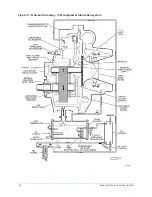
Refrigerant flow to the evaporator is controlled by a variable orifice.
A level sensor senses the refrigerant level in the condenser and outputs an analog voltage to
the microboard that represents this level (0% = empty; 100% = full). Under program control,
the microboard modulates a variable orifice to control the condenser refrigerant level to a
programmed setpoint. Other setpoints affect the control sensitivity and response. These setpoints
must be entered at chiller commissioning by a qualified service technician. Only a qualified service
technician can modify these settings.
While the chiller is shut down, the orifice is in the fully open position causing the sensed level to be
approximately 0%. When the chiller is started, after the vane motor end switch (VMS) opens when
entering
SYSTEM RUN
, if the actual level is less than the level setpoint, a linearly increasing ramp
is applied to the level setpoint. This ramp causes the setpoint to go from the initial refrigerant level
(approximately 0%) to the programmed setpoint over a programmable period of time.
If the actual level is greater than the setpoint when the VMS opens, there is no pulldown period, it
immediately begins to control to the programmed setpoint.
While the chiller is running, the refrigerant level is normally controlled to the level setpoint.
However, anytime the vanes fully close (VMS closes), normal level control is terminated, any
refrigerant level setpoint in effect is cancelled and the outputs to the level control are constantly
open.
Optional service isolation valves
If your chiller is equipped with optional service isolation valves on the discharge and liquid line,
these valves must remain open during operation. These valves are used for isolating the refrigerant
charge in either the evaporator or condenser to allow service access to the system. A refrigerant
pump-out unit is required to isolate the refrigerant.
CAUTION
Isolation of the refrigerant in this system must be performed by a qualified service technician.
Optional hot gas bypass
Hot gas bypass is optional and is used to eliminate compressor surge during light load or high
head operation. The OptiView™ control panel automatically modulates the hot gas valve open
and closed as required. Adjustment of the hot gas control valve must be performed by a qualified
service technician following the Hot Gas Set-up procedure.
Note:
Changes in chilled water flow require re-adjustment of the hot gas control to ensure
correct operation.
Model YK Style G R-134a or R-513A
24

