background image

JOHNSON CONTROLS

18

FORM   50.40-OM1 (713) 

ISSUE DATE: 07/17/2013

SECTION 2 - OPERATION

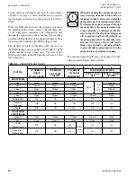
TABLE 8 - 

PRESSURE DIFFERENCE FOR DE-

TERMINING PRESENCE OF NON-CONDENSIBLE 
GASES

REFRIGERANT

DIFFERENCE BETWEEN GAUGE

READING AND SATURATED

PRESSURE

PSIG

KPA

CFC-11

27.6

CFC-114

27.6

HFC-123

27.6

CFC-12

41.4

HFC-134a

6

41.4

CFC-500

8

55.1

HCFC-22

10

69.0

CFC-502

10

69.0

CHARGING REFRIGERATION UNIT WITH 

REFRIGERANT FROM RSR UNIT
Gas Charging

When it is time to transfer the refrigerant from the RSR 

to the refrigeration unit, the latter must first be charged 

with gas.
This is particularly true of refrigeration units contain-

ing liquid coolers and/or water cooled condensers. If 

liquid refrigerant is charged in the unit when the unit 

pressure is lower than the saturation pressure equiva-

lent to 32°F (0°C), the water tubes can freeze and burst 

even though water is being pumped through the tubes.
Set the water flow and valves as shown in column 4 

Table 6 on page 16

When the valves are set, refrig-

erant gas will flow into the refrigeration unit because 

of the higher pressure in the RSR. The RSR compres-

sor does not have to run during gas charging.
When the refrigeration unit pressure is above the satu-

ration pressure equivalent to 32°F (0°C) (Table 8) or 

when the pressure has equalized, close all of the valves.
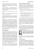
On RSR Models 1100 and 1600 and on Easy Tank™ 

Models RT 1100 and 1600, an electric heater is in-

stalled on the bottom of the storage vessel to increase 

the pressure of the stored refrigerant when the RSR is 

subjected to low ambient temperatures.

Charging with Liquid Refrigerant

Set the valves and pumps as indicated in column 5 of 

Table 

6 on page 16

. Turn the toggle switch on the RSR to the 

ON position.

Refrigerant vapor will be pulled off of the top of the refrig-

eration unit condenser, raised to a higher pressure by the 

RSR compressor, condensed to liquid in the RSR conden ser, 

and then returned to the refrigeration unit as a liquid.
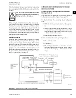
The level of liquid in the storage vessel can be observed 

through the sight glasses in the vessel. When the liquid has 

been exhausted from the storage vessel, close valves 6 and 

7 and simultaneously shut OFF the RSR toggle switch.

Removal of Refrigerant from Hoses and Storage 

Vessel

Before removing the hoses between the RSR and the 

refrig eration unit, open valves 1 and 3 on the manifold 

and close valves 2 and 4. Start the RSR compressor and 

open valve 7 simultaneously. Valve 5 should be open 

and valve 6 closed.
Run the RSR compressor until a vacuum of at least 

29 in. Hg. exists in the storage vessel. At this point, 

close valve 7 and simultaneously move the RSR toggle 

switch to the OFF position. Close manifold valves 1, 2, 

3, and 4, as well as valve 5. The hose valves can then 

be closed and the hoses removed from the refrigeration 

unit.

TABLE 9 - 

VAPOR PRESSURE – CFC-11, CFC-12, 

CFC-22 AND CFC-500

TEMP.

(°F)

VAPOR PRESSURE*

CFC-11 CFC-12 CFC-22 CFC-500

-150

29.9

29.6

29.4

-140

29.9

29.4

29.0

-130

29.9

29.1

28.4

-120

29.9

28.6

27.7

-110

29.8

28.0

26.5

-100

29.8

27.0

25.0

26.4

-90

29.7

25.7

23.0

24.9

-80

29.6

24.1

20.2

22.9

-70

29.4

21.8

16.6

20.3

-60

29.2

19.0

12.0

17.0

-50

28.9

15.4

6.2

12.8

-40

28.4

11.0

0.5

7.6

-35

28.1

8.4

2.6

4.6

-30

27.8

5.4

4.9

1.2

-25

27.4

2.3

7.4

1.2

-20

27.0

0.6

10.2

3.2

-15

26.5

2.4

13.2

5.4

-10

26.0

4.4

16.4

7.8

-5

25.4

6.7

20.1

10.4

0

24.7

9.2

24.0

13.3

Summary of Contents for YORK EASYTANK LD17584

Page 1: ...ER COOLED REFRIGERANT RECOVERY AND RECYCLING UNITS OPERATION MAINTENANCE Supersedes 50 40 OM1 904 Form 50 40 OM1 713 Issue Date July 17 2013 RSR UNITS LD17583 PORTABLE RECOVERY PAK LD17585 EASYTANK LD17584 ...

Page 2: ...rials This individual shall also be familiar with and comply with all applicable governmental standards and regulations pertaining to the task in question SAFETY SYMBOLS The following symbols are used in this document to alert the reader to specific situations Indicates a possible hazardous situation which will result in death or serious injury if proper care is not taken Indicates a potentially h...

Page 3: ...n Controls QuickLIT website at http cgproducts johnsoncontrols com Operating service personnel maintain responsibility for the applicability of these documents to the equipment If there is any question regarding the applicability of these documents the technician should verify whether the equipment has been modified and if current litera ture is available from the owner of the equipment prior to p...

Page 4: ...JOHNSON CONTROLS 4 FORM 50 40 OM1 713 ISSUE DATE 07 17 2013 THIS PAGE INTENTIONALLY LEFT BLANK ...

Page 5: ...igerant Recovery 13 Operation of Refrigerant Storage Recycle System 15 Liquid Transfer Refrigeration Unit to RSR Storage Vehicle 15 Detection and Removal of Non Condensible Gases 17 Charging Refrigeration Unit with Refrigerant From RSR Unit 18 SECTION 3 DIAGRAMS 23 SECTION 4 MAINTENANCE PROCEDURES 29 General 29 Compressor Model CFC 1000 31 SECTION 5 REPLACEMENT PARTS AND KITS 33 Compressor Replace...

Page 6: ...tandard and Metric 11 TABLE 4 Standard Tank Options Standard and Metric 12 TABLE 5 Settings for Pressure Safety Control Switches 13 TABLE 6 Operation Settings 16 TABLE 7 Final Vacuum EPA Regulatiions 17 TABLE 8 Pressure Difference for Determining Presence of Non Condensible Gases 18 TABLE 9 Vapor Pressure CFC 11 CFC 12 CFC 22 and CFC 500 18 TABLE 10 Vapor Pressure HCFC 123 and HFC 134a 19 TABLE 11...

Page 7: ... job site all containers should be opened and contents checked against the packing list Any material shortage should be reported to Johnson Controls immediately Refer to Shipping Damage Claims Form 50 15 NM SAFETY SUMMARY Installation and servicing of air conditioning equipment and support equipment can be hazardous because of system pressures and the presence of dangerous volt ages Only trained a...

Page 8: ...gned and stamped in accordance with the ASME Boiler and Pressure Vessel Code The ves sel is pitched toward the receiver drain to allow total removal of liquid Valves And Hoses The unit has permanent mounted ball valves to allow the unit to remove replace or distill refrigerant without hav ing to break hoses to the chiller Eight feet of heavy duty refrigerant hoses with flare fittings are included ...

Page 9: ...s Yes DESCRIPTION MODEL RSR 2212 RSR 2222 RSR 4436 RSR 4445 Refrigerant CFC 12 500 502 CFC 12 500 502 CFC 12 500 502 CFC 12 500 502 HCFC 22 HCFC 22 HCFC 22 HCFC 22 HFC 134a HFC 134a HFC 134a HFC 134a Refrigerant Storage Capacity Lbs 80 Full at 90 F Refrigerant Lbs Refrigerant Lbs Refrigerant Lbs Refrigerant Lbs CFC 12 1240 CFC 12 2166 CFC 12 3976 CFC 12 5684 HCFC 22 1126 HCFC 22 1966 HCFC 22 3612 ...

Page 10: ... Yes Yes Yes Yes DESCRIPTION MODEL RSR 2212 RSR 2222 RSR 4436 RSR 4445 Refrigerant CFC 12 500 502 CFC 12 500 502 CFC 12 500 502 CFC 12 500 502 HCFC 22 HCFC 22 HCFC 22 HCFC 22 HFC 134a HFC 134a HFC 134a HFC 134a Refrigerant Storage Capacity kg 80 Full at 32 C Refrigerant kg Refrigerant kg Refrigerant kg Refrigerant kg CFC 12 562 CFC 12 992 CFC 12 1804 CFC 12 2265 HCFC 22 511 HCFC 22 900 HCFC 22 163...

Page 11: ...udes replaceable catch all type filters with singlecore 48 cubic inches 786 ccm Refrigerant Compressor High Pressure Units The high pressure units for refrigerants CFC 12 HCFC 22 CFC 500 CFC 502 and HFC 134a feature a reciprocating compressor that is capable of pulling a vacuum to a level which is in accordance with EPA regulations See Table 7 on page 17 Refrigerant Vacuum Pump The low pressure un...

Page 12: ...4a 1140 517 24 x 84 609 x 2134 1000 454 RT 2222 CFC 12 2166 982 30 x 93 1 4 702 x 2368 1300 590 HCFC 22 1966 906 30 x 93 1 4 702 x 2368 1300 590 CFC 500 1937 879 30 x 93 1 4 702 x 2368 1300 590 CFC 502 2044 928 30 x 93 1 4 702 x 2368 1300 590 HFC 134a 1992 904 30 x 93 1 4 702 x 2368 1300 590 RT 4436 CFC 12 3976 1804 36 x 119 914 x 3022 2700 1225 HCFC 22 3612 1639 36 x 119 914 x 3022 2700 1225 CFC ...

Page 13: ...to con form to the design working pressure of the RSR storage ves sel and the upper limit for satisfactory Table 5 SETTINGS FOR PRESSURE SAFETY CONTROL SWITCHES REFRIGERANT CUT OUT CUT IN HIGH PRESSURE LOW PRESSURE HIGH PRESSURE LOW PRESSURE PSIG KPA IN HG KPA PSIG IN HG KPA CFC 12 HFC 134a 150 1034 20 68 Manual Reset 10 34 CFC 500 180 1241 20 68 Manual Reset 10 34 CFC 502 250 1724 20 68 Manual Re...

Page 14: ... cess will help you determine the normal period of operation before an oil change is required See SECTION 4 MAINTENANCE PROCEDURES for Low Pressure Units for the correct procedure to add or remove oil from the vacuum pump and oil separator Filter Dryer Replacement Element The RSR unit contains a filter dryer that removes moisture acids as well as solid particles from the re frigerant that is being...

Page 15: ...he RSR unit the pressure should be relieved to the atmosphere and the vessel evacuated with a vacuum pump to a vacuum of 29 inches of mercury Evacuate using gas connection con nection between valves 1 2 open valves 1 2 3 4 during evacuation close valve 5 See Figure 1 on page 15 Figure 1 YORK RSR SYSTEM FLOW DIAGRAM LD01105 OPERATION OF REFRIGERANT STORAGE RECYCLE SYSTEM Liquid Transfer Refrigerati...

Page 16: ... STEP 1 GAS OFF STEP 2 LIQUID CHARGE RSR SYSTEM Valve 1 Open Closed Open Open 1 4 or 2 3 Closed Valve 2 Closed Open Closed Open Valve 3 Open Closed Open Closed Valve 4 Closed Open Closed Open Valve 5 Open Closed Closed Closed Open Compressor On On On Off On Water to Condenser Off On Off Off On Heater Off Off On Off On CHILLER AIR CONDITIONER Valve 6 Open Closed Closed Closed Open Valve 7 Open Open...

Page 17: ...checked If the pressure has risen due to residual refrigerant re maining in the refrigeration unit the Gas Pump Out procedure must be repeated until a pressure rise is not detected after a five minute waiting period Table 7 FINAL VACUUM EPA REGULATIIONS DESCRIPTION FINAL VACUUM IN HG KPA HCFC 22 unit containing less than 200 Lbs 91 kg of refrigerant 0 0 HCFC 22 unit containing more than 200 Lbs 91...

Page 18: ...harging with Liquid Refrigerant Set the valves and pumps as indicated in column 5 of Table 6 on page 16 Turn the toggle switch on the RSR to the ON position Refrigerant vapor will be pulled off of the top of the refrig eration unit condenser raised to a higher pressure by the RSRcompressor condensedtoliquidintheRSRconden ser and then returned to the refrigeration unit as a liquid The level of liqu...

Page 19: ...9 11 8 28 2 16 4 15 22 1 17 7 37 7 23 3 20 21 2 21 0 43 0 27 2 25 19 9 24 6 48 8 31 4 30 18 6 28 4 54 9 36 0 35 17 2 32 6 61 4 40 8 40 15 6 37 0 68 5 46 0 45 13 9 41 7 76 0 51 6 50 12 0 46 7 84 0 57 5 55 10 0 52 1 92 6 63 9 60 7 8 57 7 101 6 70 6 65 5 4 63 8 111 2 77 8 70 2 8 70 2 121 4 85 3 75 0 0 77 0 132 2 93 4 80 1 5 84 2 143 6 101 9 85 3 2 91 8 155 7 111 0 90 4 9 99 8 168 4 120 4 95 6 8 108 2...

Page 20: ...3 40 0 4384 10 22 560 42 1 0909 8 24 158 44 1 7652 6 25 808 46 2 4615 4 27 511 48 3 1805 2 20 268 50 3 9226 0 31 080 52 4 6883 2 32 948 54 5 4781 4 34 873 56 6 2924 6 36 856 58 7 1318 8 38 898 60 7 9967 10 41 001 62 8 8877 15 46 530 64 9 8053 20 52 459 66 10 750 25 58 807 68 11 722 30 65 591 TEMP F VAPOR PRESSURE PSIG TEMP F VAPOR PRESSURE PSIG CFC 114 CFC 502 70 12 722 35 72 827 72 13 751 40 80 5...

Page 21: ... 0 531 912 644 26 7 10 581 990 703 29 4 22 633 1074 765 32 2 34 688 1161 830 35 0 47 746 1254 900 37 8 61 808 1351 973 40 6 75 873 1453 1049 43 3 90 940 1561 1131 46 1 108 1012 1673 1216 TEMP C VAPOR PRESSURE KPA CFC 11 CFC 12 CFC 22 CFC 500 51 7 145 1166 1916 1398 54 4 165 1248 2046 1496 57 2 187 1334 2183 1598 60 0 210 1425 2325 1706 62 8 234 1519 2475 1818 65 6 260 1618 2630 1935 Vapor pressure...

Page 22: ...7 12 2 21 1 178 7 8 17 0 20 0 190 8 9 21 9 18 9 202 10 0 27 0 17 8 214 11 1 32 3 16 7 227 12 2 37 8 15 6 240 13 3 43 4 14 4 254 14 4 49 2 13 3 268 15 6 55 1 12 2 283 16 7 47 5 9 4 321 17 8 67 6 6 7 362 18 9 74 1 3 9 405 TEMP C VAPOR PRESSURE KPA TEMP C VAPOR PRESSURE KPA CFC 114 CFC 502 20 0 80 8 1 1 452 21 1 87 7 1 7 502 22 2 94 8 4 4 555 23 3 102 1 7 2 612 24 4 109 6 10 672 25 6 117 3 12 8 735 2...

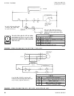
Page 23: ...Vacuum Pump HP Contact High Pressure HTR Heater Refrigerant Storage Vessel 1000 Watt HTR Heater Oil Separator 25 Watt LS Switch Liquid Level 1 R Relay Liquid Level Switch w N O contact LEGEND SW Switch On Off Compressor Motor HP LP Switch Pressure Combination Hi LO LS Switch Liquid Level 1 R Relay Float Switch N O contact 2 R Relay Motor Circuit N O contact HTR Heater Oil Separator Figure 3 WIRING...

Page 24: ...ntrol circuit Johnson Controls supplies mating Twist Lock plug for field wiring connection by customer 1 flex cord with special interlock plug supplied by Johnson Controls for wiring to customer s Pumpout vessel pressure liquid level switch Legend SW Switch On Off Compressor HP LP Switch Pressure Combination Hi Lo Control LS Switch Liquid Level 1 R Relay Liquid Level N O contact M Contactor Compre...

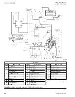
Page 25: ...P Cutout Tank 2 Motor 9 Ball Valves 19 HP Cutout Compressor 3 Drive Package 10 Filter Dryer 20 Junction Box Motor Pulley 1 Core Switch Compressor Compressor Pulley 11 Moisture Indicator Switch Heater Belt 12 Low Pressure Vessel 21 Refrigerant Hoses Base for Unit 13 Relief Assembly 22 Valve 4 Belt Guard 14 Sight Glass 23 Power Wire 5 Gauges 15 Casters 24 Purge Valve 6 Oil Separation 16 Heater 7 Hea...

Page 26: ...ssure Switch 3 Drive Package 10 Filter Dryer 20 Junction Box Motor Pulley 1 Core Switch Compressor Compressor Pulley 11 Moisture Indicator Switch Heater Belt 12 High Pressure Vessel 21 Refrigerant Hoses Base for Unit 13 Relief Assembly 22 Valve 4 Belt Guard 14 Sight Glass 23 Power Wire 5 Gauges 15 Casters 6 Oil Separation 16 Purge Valve 7 Heater 17 Float Switch Figure 7 PIPING DIAGRAM RSR 2212 222...

Page 27: ...ION ITEM DESCRIPTION 1 Vacuum Pump 9 Ball Valves 17 Power Wire 2 Motor 10 Filter Dryer 18 Customer Service Valve 3 Drive Package 11 Moisture Indicator 4 Belt Guard 12 Wheels Pulleys Compressor 13 Relief Valve Pulleys Motor 14 Pressure Control 5 Gauges 15 Junction Box 6 Oil Separator Switches 7 Heater Oil Separator Remote Pressure Interlock 8 Condenser 16 Refrigerant Hoses LD17569 ...

Page 28: ...JOHNSON CONTROLS 28 FORM 50 40 OM1 713 ISSUE DATE 07 17 2013 THIS PAGE INTENTIONALLY LEFT BLANK ...

Page 29: ... taut to create excessive bearing loads Due to the pulsating load created by the compressor the belt tension must be greater than for a normal steady load Belt tension can be accurately determined with the use of a belt tension gauge which gives a direct reading of belt load as determined by the deflection A tension of 100 Ibs is considered to be the normal belt tension After 36 to 48 hours of ope...

Page 30: ...rator to purge air from the compressor and oil separator 11 Open the manifold valves as required for the next re covery operation Adding or Changing Oil Low Pressure Unit The procedure for the vacuum pump is essentially the same as that for the compressor the main excep tion being the use of DuoSeal vacuum pump oil in the pump oil sump and in the oil separator It is recommended that the vacuum pum...

Page 31: ...m of 30 psig Thoroughly check the compres sor and all refrigerant holding components for leaks 2 If no leaks are found close the suction service valve and run compressor until compressor suc tion pressure is 0 psig 3 Stop compressor Observe discharge pressure and if it remains constant the discharge valves of the valve assem bly are holding properly If pressure drops more than 5 Ibs 34 5 kPa in on...

Page 32: ...ial adhering to the head valve plate or cylinder should be carefully removed in such a manner that the machined sealing surfaces are not scratched or nicked Installation of Head and Valve Plate 1 Apply a thin film of clean YORK Refrigeration oil on the area of the crankcase to be covered by the cylinder gasket Place the cylinder gasket in position on the cylinder so the dowel pins in the crankcase...

Page 33: ...CTION 5 REPLACEMENT PARTS AND KITS Figure 9 COMPRESSOR REPLACEMENT PARTS MODEL CFC 1000 1 Gasket Kit BMK 683 7 contains one complete set of all gaskets 2 Parts included inside broken lines are sold as kits per B M shown Example BMK 680 6 would be 3 parts only LD17582 ...

Page 34: ... SAE 2 31071 19 Screw Seal Plate 6 10112 7 21 Seal Assembly 1 CBS 2938 665 8 22 O Ring 1 5045R 665 8 683 7 23 O Ring 1 30525 683 7 24 Plate Rear Bearing Housing 1 41268 1 25 Snap Ring Rear Bearing Housing 1 27022 26 Oil Sight Glass With O Ring 1 CBL 724 27 Plug Oil Filter 2 5046R 28 Serial Plate 1 52575 29 Drive Screw Serial Plate 2 3895 30 O Ring Bottom Plate 1 30521 683 7 31 Bottom Plate 1 245 4...

Page 35: ... Gasket Kit BMK679 1 Valve Plate Kit BMK665 8 Seal Kit BMK680 6 Crankshaft and Bearing Kit BMK695 1 Piston and Rod Kit Standard BMK695 2 Piston and Rod Kit 020 Oversize BMK679 3 Valve Plate Kit Cad Nickel Plated Components in the valve plate kit seal kit piston and rod kit and the crankshaft kit are shown within an area enclosed by a line on the drawing on Figure 9 on page 33 COMPRESSOR MODEL 1679...

Page 36: ...vity seating it firmly and squarely 8 Slide end plate on shaft and press it in as far as it will go Do not allow it to spring out or move backward Tighten screws or bolts uniformly to keep the face of the seat at right angles to shaft Tightening of end plate automatically sets seal in proper position Be sure to use the torque require ment specified for the seal assembly See Table 18 on page 36 Aft...

Page 37: ...JOHNSON CONTROLS 37 SECTION 5 REPLACEMENT PARTS AND KITS FORM 50 40 OM1 713 ISSUE DATE 07 17 2013 5 LD01115 Figure 10 COMPRESSOR REPLACEMENT PARTS DISCONTINUED MODEL 16799 ...

Page 38: ... Piston Ring 12 16711 14 Clamping Stud 2 16731 15 Lock Washer 1 2 heavy 2 30013 16 Hex Nut 1 220NF 2 2 30012 17 Sight Glass Gasket 2 16807 18 Sight Glass 1 16811 19 Sight Glass Retaining Ring 1 16809 851 Sight Glass Assembly 1 16808 20 Shaft End Plate 1 16727 21 Shaft End Plate Gasket 1 16726 22 Suction Screen 2 16725 23 Service Valve Gasket 5 16728 24 Oil Fill and Drain Plug 2 16729 25 Crankcase ...

Page 39: ...he cylinder head using a good solvent as a cleaning agent 4 Thoroughly clean the top of the pistons and the cyl inder flange The most efficient manner in which to accomplish this is to bring one piston flush with the top of the cylinder and clean the top of the piston and approximately one half of the cylinder flange in one operation This process should be repeated for each cylinder using a good s...

Page 40: ...JOHNSON CONTROLS 40 FORM 50 40 OM1 713 ISSUE DATE 07 17 2013 SECTION 5 REPLACEMENT PARTS AND KITS LD03861 Figure 11 COMPRESSOR REPLACEMENT PARTS MODELS RA AND CK ...

Page 41: ...asher 3 12031 505 8 14 Valve Screw 3 33160 505 8 15 Discharge Valve Nut 3 11212 505 8 16 Lockwasher 3 12307 505 8 17 Cylinder Head 1 24016 18 Capscrew Cylinder Head 18 33162 19 Gasket Adapter Plate 1 30047 507 2 20 Adapter Plate 1 41176 21 Capscrew 2 10020 12 22 Gasket Discharge S O V 1 30048 507 2 23 Discharge S O V 1 31012 1 24 Screw 2 10012 6 25 Connector Tube 1 34150 26 Gasket Suction S O V 1 ...

Page 42: ...er Bearing Assembly 1 41099 1 509 4 63 Gasket Housing Cover 1 30060 507 2 509 4 64 Seal Guard 1 41145 65 Lock Washer 2 12109 66 Machine Screw 2 10106 C6 67 Drive Screw 2 10403C 68 Serial Plate 1 CBW2641 69 Screw 4 33251 70 Lockwasher 4 2177 71 Counterweight 2 23520 1 72 Crankshaft 1 22518 5 675 7 73 Key 1 CBW2625 675 7 74 Nut 6 11030 AI606 1 75 Lock Washer 6 2174 AI606 1 76 Connecting Rod 3 AI606 ...

Page 43: ...ree from leaks and sufficient suction exists but the discharge pressure is insuf ficient there are several sources to the problem A simple explanation there is an insufficient flow of refrigerant vapor into the vacuum pump Check to see that the tubing con necting the suction port to the chiller is not obstructed A low oil level or V belt slippage can cause the same symp toms If there is a leak in ...

Page 44: ... 3 8 6 2 00 2706 14 Hex Hd Cap Screw 1 4 20 x 3 4 10 2 01 0112 15 Split Lockwasher 3 4 10 2 63 0193 16 Large End Plate 1 61 8416D 17 Oil Case Gasket 1 41 0403 19 Washer 6 41 2363 21 Washer 1 41 0508 22 Shaft 1 41 1762 23 Woodruff Key 3 41 0624 24 Retaining Ring 1 4 06 0754 25 Oil Case Assy See Note 1 1 61 8417D 27 Plug Oil Fill 1 41 2933 28 O Ring 1 61 8420 29 Oil Level Window See Note 4 2 61 8418...

Page 45: ...e chamber cover The importance of a gasketed seam is determined principally by its function If it is a vacuum seal the ultimate performance of the pump is dependent upon it If it is an oil seal the pump may be operated satisfactorily for some time without loss of function Eventually of course a great loss of oil may cause harmful damage Repairing Technique Thin composition gaskets are generally us...

Page 46: ...JOHNSON CONTROLS 46 FORM 50 40 OM1 713 ISSUE DATE 07 17 2013 SECTION 5 REPLACEMENT PARTS AND KITS LD17570 Figure 13 COMPRESSOR DATA SHEET MODEL 51VSM ...

Page 47: ...HNSON CONTROLS 47 SECTION 5 REPLACEMENT PARTS AND KITS FORM 50 40 OM1 713 ISSUE DATE 07 17 2013 5 LD17571 Figure 14 COMPRESSOR DIMENSIONS ENGLISH 51VSM LD17576 Figure 15 COMPRESSOR DIMENSIONS METRIC 51VSM ...

Page 48: ...JOHNSON CONTROLS 48 FORM 50 40 OM1 713 ISSUE DATE 07 17 2013 LD17572 Figure 16 COMPRESSOR PARTS 51VSM ...

Page 49: ...JOHNSON CONTROLS 49 SECTION 5 REPLACEMENT PARTS AND KITS FORM 50 40 OM1 713 ISSUE DATE 07 17 2013 5 LD17573 Table 23 COMPRESSOR PARTS 51VSM ...

Page 50: ...JOHNSON CONTROLS 50 FORM 50 40 OM1 713 ISSUE DATE 07 17 2013 SECTION 5 REPLACEMENT PARTS AND KITS LD17574 Figure 17 COMPRESSOR MAINTENANCE INSTRUCTIONS 51VSM ...

Page 51: ...RPM HP REQUIRED TC F EVAPORATING TEMPERATURE F H M L H M L 41 32 23 14 5 4 13 22 31 40 51VSM 800 15 15 15 86 157200 130820 106690 85120 68910 53660 40650 30350 21780 14440 20 15 15 104 142870 113660 91440 73040 59220 43830 33010 23280 16420 11570 20 20 15 122 119390 99730 79080 63520 50650 37610 26520 18710 13180 9290 1000 15 15 15 86 196490 163520 133380 106390 86150 67070 50820 37920 27200 18060...

Page 52: ...JOHNSON CONTROLS 52 FORM 50 40 OM1 713 ISSUE DATE 07 17 2013 SECTION 5 REPLACEMENT PARTS AND KITS Table 26 COMPRESSOR CROSS REFERENCE CHART 51VSM LD17578 Table 27 COMPRESSOR SPECIFICATIONS 51VSM LD17579 ...

Page 53: ... Celsius multiply by 5 9 or 0 5556 Example 10 0 F range x 0 5556 5 6 C range Table 28 SI METRIC CONVERSION MEASUREMENT MULTIPLY ENGLISH UNIT BY FACTOR TO OBTAIN METRIC UNIT Capacity Tons Refrigerant Effect ton 3 516 Kilowatts kW Power Horsepower 0 7457 Kilowatts kW Flow Rate Gallons Minute gpm 0 0631 Liters Second l s Length Feet ft 0 3048 Meters m Inches in 25 4 Millimeters mm Weight Pounds lbs 0...

Page 54: ...ia USA 17405 1592 800 861 1001 Subject to change without notice Printed in USA Copyright by Johnson Controls 2013 www johnsoncontrols com ALL RIGHTS RESERVED Form 50 40 OM1 713 Issue Date July 17 2013 Supersedes Form 40 40 OM1 904 ...

Reviews: