


1083286-UIM-L-1219
8
Johnson Controls Ducted Systems
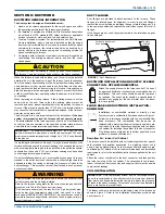
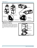
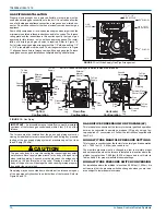
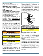
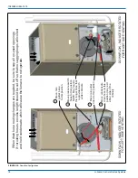
DOWNFLOW APPLICATION
To apply the furnace in a downflow position, it will be necessary to
rotate the vent blower 90
°
left or right so that the vent pipe passes
through the side of the furnace casing. See Figure 7.
FIGURE 7:
Downflow Venting
LEFT SIDE VENT
RIGHT SIDE VENT
Rotate vent
blower 90°
either way
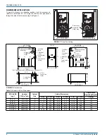
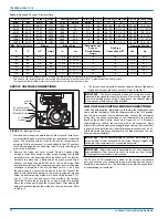
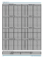
FIGURE 8:
Dimensions
)5217
$
/()76,'(
&RPEXVWLRQ$LU,QOHW
&RQGHQVDWH'UDLQ
'RZQIORZ
7KHUPRVWDW
:LULQJ
´
*DV3LSH
(QWU\
(OHFWULFDO
(QWU\
&RQGHQVDWH
'UDLQ
7KHUPRVWDW
:LULQJ
5,*+76,'(
&RQGHQVDWH'UDLQ
'RZQIORZ
´
´
´
´
&RPEXVWLRQ$LU,QOHW
*DV3LSH
(QWU\
(OHFWULFDO
(QWU\
&RQGHQVDWH
'UDLQ
2SWLRQDO5HWXUQ$LU
&XWRXW(LWKHUVLGH
´
)RU&ODGGHGGRRUDGGDSSR[LPDWHO\DQDGGLWLRQDO´
&
6833/<(1'
´
´
´
%
´
´
´
&RPEXVWLRQ
$LU,QOHW
5(7851(1'
%
´
´9HQW
&RQQHFWLRQ
2XWOHW
´9HQW
&RQQHFWLRQ
2XWOHW
´9HQW
&RQQHFWLRQ
2XWOHW
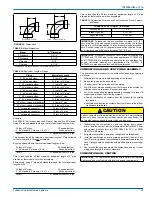
Table 2:
Cabinet and Duct Dimensions
BTUH (kW)
Input
Nominal
CFM (m
3
/min)
Cabinet
Size
Cabinet Dimensions
Approximate
Operating Weights
A (in)
A (cm)
B (in)
B (cm)
C (in)
C (cm)
Lbs (kg)
60 (17.6)
1200 (34.0)
B
17 1/2
44.4
16 3/8
41.6
13 1/4
33.7
122
80 (23.4)
1200 (34.0)
B
17 1/2
44.4
16 3/8
41.6
14 3/4
37.5
126
80 (23.4)
1600 (45.3)
C
21
53.3
19 7/8
50.5
16 1/2
41.9
136
100 (29.3)
1600 (45.3)
C
21
53.3
19 7/8
50.5
18 1/4
46.4
142
100 (29.3)
2000 (56.6)
C
21
53.3
19 7/8
50.5
18 1/4
46.4
145
120 (35.1)
2000 (56.6)
D
24 1/2
62.2
23 3/8
59.4
21 3/4
55.2
156