


100.210-IOM (FEB 2015)
Page 17
VYPER
™
VARIABLE SPEED DRIVE
INSTALLATION
Installation
RIGGING AND HANDLING
Each.Vyper
™
.Variable.Speed.Drive.unit.is.shipped.mounted.on.
a.wooden.skid.or.mounted.to.the.refrigeration.package..All.
shipping.materials.must.be.removed.prior.to.unit.installation.
The.Vyper
™
.cabinet.unit.is.best.moved.via.lifting.lugs.on.the.
top.sides.of.the.cabinet..Caution.must.be.used.to.not.damage.
the.pump.or.peripheral.equipment.on.the.rear.of.the.cabinet...
Never.move.the.unit.by.pushing.against.the.Vyper
™
.cabinet.
with.a.forklift.or.other.machinery.
UNIT (WITH FILTER) WEIGHTS (lb)
MODEL
UNIT
UNIT AS SHIPPED
700/572
1,890
2,319
912/752
2,026
2,455
VYPER
™
MOUNTING CONFIGURATIONS
NOTICE
When mounting the Vyper™ unit, allow space for ser-
vicing both sides of the unit cabinet.
The.Frick.Vyper
™
.is.offered.in.two.mounting.configurations,.
package.mounted.and.remote.mounted.
PACKAGE MOUNTED UNITS
One.advantage.of.the.package.mounted.version.is.that.all.
electrical. connections. have. been. prewired. and. tested. at.
the.factory.which.ensures.proper.installation.of.control.and.
power. lines.. Package. mounting. is. available. for. all. horse-
power.ratings.of.the.Vyper
™
..Both.water.or.glycol.cooling.
connections.are.also.available.as.well.as.the.optional.IEEE.
519.harmonic.filter..In.addition,.the.package-mounted.Vyper
™
.
does.not.require.an.additional.dV/dt.filter.between.the.VFD.
cabinet.and.the.motor..
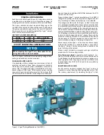
Figure.6.shows.Vyper
™
.
.cabinet.mounted.on.a.Frick.RWF.II.
refrigeration.package..Individual.systems.configurations.will.
vary.according.to.model.and.horsepower.sizes.selected.
On.package.mounted.units,.the.Vyper
™
.
.cabinet.is.mounted.
on.a.rectangular.welded.steel.channel,.which.provides.both.
an.attachment.point.for.the.cabinet’s.side.brackets.and.also.
helps.to.maintain.the.rigidity.of.the.cabinet.during.service...
The.channel.assembly./.VSD.cabinet.is.mounted.on.two.ex-
tension.brackets.welded.to.pads.on.the.system’s.oil.separa-
tor..All.package-mounted.units.are.assembled.with.vibration.
isolators.located.between.the.Vyper
™
.
.channel.frame.and.the.
extension.mounting.brackets..The.isolators.help.to.minimize.
the. exposure. of. internal. components. and. connections. to.
cyclic.vibrations.during.unit.shipping.and.operation.
Power.supply.to.the.Vyper
™
.
.is.from.the.top..Power.supply.
to.the.motor.is.made.via.a.conduit.exit.from.a.rear.panel.in.
the.Vyper
™
.
.Cabinet..Control.wiring.in/out.is.located.at.the.
lower.left.side.of.the.cabinet.
Please. consult. standard. compressor. package. installation.
procedures.for.this.mounting.method.
Drive Disconnect Height –
.covered.under.Exception.2,.sec-
tion.8.of.article.404.of.the.NEC,.which.states,.Switches.and.
Circuit.Breakers.installed.adjacent.to.motors,.appliances,.or.
other.equipment.that.they.supply.shall.be.permitted.to.be.
located.higher.than.2.0.M.(6.ft.7in).and.to.be.accessible.by.
portable.means.
REMOTE MOUNTED UNITS
For. the. remote. mounting. method,. the. Vyper
™
. cabinet. is.
mounted.on.a.steel.base.specifically.designed.for.the.VSD...
The.primary.requirement.for.mounting.the.Vyper
™
.is.that.
Figure 6 - Vyper
™
Package mounted on Frick rWF II.