


Network Room Module Technical Bulletin
23
Procedure Overview
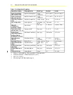
Table 9: Installing and Commissioning the Network Room Module
To Do This
Follow These Steps
Open the Room Command
Module
Insert the pointed tool or special tool available from Johnson Controls into
the narrow slot at the center top of the module. While pressing down gently,
pry the cover away from the base. In North American models, the
anti-tamper screw must first be removed.
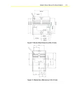
Mount the NRM directly on
a wall surface
Hold the module base on the wall to cover the electrical outlet and mark the
position of at least two holes. Drill holes and insert plastic plugs (wall
anchors) into holes if required. Mount the module base on the wall and
secure with at least two screws. Use insulating material to prevent air from
the wiring channel from entering the room module.
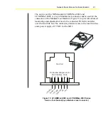
Mount the NRM
(80 x 80 mm) on a wall
surface using the Plastic
Base for Surface Mounting
Remove one of the conduit notches on the plastic base for surface
mounting. Mark the position of the holes on the wall and drill holes 5 mm in
diameter. Insert plastic plugs (wall anchors) into holes. Position and fix the
mounting base to the wall using the two long screws provided in the kit. Fix
the base of the NRM to the surface mounting base using the two short
screws provided in the kit.
Mount the NRM
(80 x80 mm) on a Recessed
Wall Box Mounting Kit
Turn the screws on the recessed wall box mounting kit to adjust the
assembly to the depth of the wall box. Insert the kit into the wall box, and
tighten the other screws until the prongs clamp properly in the wall box.
Mount the NRM module base on the kit by inserting the two screws included
in the kit into two opposite holes of the kit.
Commission the NRM
Connect and check the power and network wiring from the module to the
FX controller. Apply power to the FX controller (or switch on the separate
power source if used). Connect the FX CommPro N2, LON, or BACnet
software tool to the FX controller to monitor the NRM network variables
within the control application. Use the setpoint dial and fan push button to
verify that the module is operating and sending and receiving valid data from
the controller.
Detailed Procedures
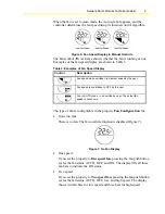
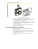
Opening the Network Room Module
To open the Network Room Module:
1.
(North American models only) Remove the anti-tamper screw in the
top of the module enclosure with a small cross-head screwdriver
(Figure 16).
2.
Remove the module cover from the base by inserting a pointed tool
into the narrow slot at the center top of the cover. A special tool is
available from Johnson Controls (see Ordering Codes).