3. Gain access to the coil section of the unit.
4. Use a soft brush to remove loose debris from sides
of the coil.
5. Use a steam-cleaning machine, starting from the
top of the coil and working downward. Clean the
leaving airside of the coil first, then the entering
airside. Use a block-off to prevent steam from
blowing through the coil and into dry sections of
the unit.
6. Repeat step 5 as necessary.
7.
Confirm that the drain line is open following the
cleaning.
8. Allow the unit to dry thoroughly before putting
the system back in service.
9.
Straighten any coil fins that may have been dam
-
aged during the cleaning process with a fin comb.
10. Replace all panels and parts and restore electrical
power to the unit.
11. Use caution to assure that any contaminated ma-
terial does not contact other areas of the unit or
building.
Properly dispose of all contaminated ma-
terials and cleaning solutions.
Coils
The frequency of required cleaning is dependent on the
operating hours of the system, filter maintenance and
efficiency as well as dirt load.
Coils may become externally fouled as
result of normal operation. Dirt on the
surface of the coil reduces its ability to
transfer heat that can result in reduced
performance, and increased operating
energy costs. If the dirt on the surface of
the coil becomes wet, which commonly oc-
curs with cooling coils, microbial growth
(mold) can result, in turn causing un-
pleasant odors and serious health related
indoor air quality problems.
Fin edges are sharp. Fins are fragile; car
must be exercised to avoid damaging fins.
Steam, Hot Water and Chilled Water Coils
Steam, hot water, and chilled water coils should be
kept clean to maintain maximum performance. If fins
become dirty, clean with steam and detergent, hot wa-
ter spray and detergent, or one of the commercially
available chemical coil cleaners. Rinse coils thorough-
ly after cleaning.
1. Disconnect all electrical power to the unit, tag and
lock out power source.
2. Put on appropriate personal protective equipment.
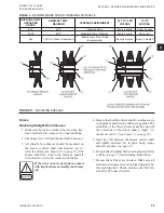
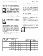
TABLE 6 -
DETERMINING DEFLECTION FORCE
BELT CROSS
SECTION
SMALLEST
SHEAVE DIAMETER
RANGE
RPM RANGE
BELT DEFLECTION FORCE
USED BELT
NEW BELT
A
3.0 - 3.6
400 - 2500
2501 - 4000
3.7
2.8
5.5
4.2
3.8 - 4.8
400 - 2500
2501 - 4000
4.5
3.8
6.8
5.7
5.0 - 7.0
400 - 2500
2501 - 4000
5.4
4.7
8.0
7.0
B
4.4 - 5.6
860 - 2500
2501 - 4000
5.3
4.5
7.9
6.7
5.8 - 8.6
860 - 2500
2501 - 4000
6.3
6.0
9.4
8.9
JOHNSON CONTROLS
28
FORM ET102.19-NOM1
ISSUE DATE:08/26/2013
SECTION 4 - PERIODIC MANINTENANCE AND SERVICE

