


SECTION 6 - LSS SETUP/CALIBRATION/SERVICE
6-10
31215923
Table 6-7. LSS Module System Interface Connector -
Power & Digital (J1 - Grey)
PIN
SIGNAL
DESCRIPTION
1
VBAT
Positive Power Supply from Host Control System (12-
24V)
2
GND
Negative Power Supply from Host Control System (0V)
3
GND-2
Connects to GND
4
N/C
Unused
5
DO1
Overload Indicator Output (Normal = VBAT / Over-
load=0V)
6
DO2
Warning Indicator Output (Normal= 0 V / Overloaded
= VBAT for 5 Sec, 0 V for 2 Sec)
7
DI3
Unused
8
DI2
Select OVERLD3 Personality Rating (No=0 V / Yes =
VBAT)
9
DI1
Select OVERLD2 Personality Rating (No=0 V / Yes =
VBAT)
10
GND-2
Connects to GND
11
VBAT-2
Connects to VBAT
12
VBAT-2
Connects to VBAT
Table 6-8. LSS Module System Interface Connector –
Communication (J1 - Black)
PIN
SIGNAL
DESCRIPTION
1
APWR
Pre-Regulated Supply for JLG Analyzer (Analyzer Pin
1; approx. 12 V)
2
TX
RS-232 for JLG Analyzer (Analyzer Pin 3)
3
TRP1
120 Ohm CANbus Terminator
4
CANH-1
CANbus Interface High
5
CANS-1
CANbus Shield Termination (Not same as GND)
6
CANH-2
Connects to CANH-1
7
CANL-2
Connects to CANL-1
8
CANS-2
Connects to CANS-1
9
CANL-1
CANbus Interface Low
10
TRP2
120 Ohm CANbus Terminator
11
RX
RS-232 for JLG Analyzer (Analyzer Pin 2)
12
GND
Ground for JLG Analyzer (Analyzer Pin 4)
Table 6-9. LSS Module Load Cell Connector Pinout (J5,
J6, J7, J8)
PIN
SIGNAL
DESCRIPTION
1
+ Signal
Positive Sensor Output (approx. 2.5 V)
2
Cal Clock
Serial Clock to Sensor’s Integrated Memory
3
- Excitation
Negative Sensor Supply Voltage (approx. 0 V)
4
+Excitation
Positive Sensor Supply Voltage (approx. 5 V)
5
- Signal
Negative Sensor Output (approx. 2.5 V)
6
Cal Data
Serial Data from Sensor’s Integral Memory
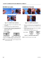
Figure 6-3. LSS Module Load Cell Connector
Pinout (J5, J6, J7, J8)
NOTE:
Physical connector as viewed looking into the
cable end
Summary of Contents for ERT2669
Page 2: ......
Page 4: ...INTRODUCTION A 2 31215923 REVISON LOG Original Issue A January 08 2021...
Page 12: ...viii 31215923 TABLE OF CONTENTS...
Page 40: ...SECTION 1 SPECIFICATIONS 1 22 31215923...
Page 58: ...SECTION 2 GENERAL 2 18 31215923...
Page 187: ...SECTION 4 BASIC HYDRAULIC INFORMATION SCHEMATICS 31215923 4 11...
Page 206: ...SECTION 4 BASIC HYDRAULIC INFORMATION SCHEMATICS 4 30 31215923...
Page 225: ...SECTION 4 BASIC HYDRAULIC INFORMATION SCHEMATICS 31215923 4 49...
Page 242: ...SECTION 4 BASIC HYDRAULIC INFORMATION SCHEMATICS 4 66 31215923...
Page 307: ...SECTION 5 JLG CONTROL SYSTEM 31215923 5 65...
Page 334: ...SECTION 6 LSS SETUP CALIBRATION SERVICE 6 12 31215923...
Page 362: ...SECTION 7 GENERAL ELECTRICAL INFORMATION SCHEMATICS 7 28 31215923...
Page 374: ...SECTION 7 GENERAL ELECTRICAL INFORMATION SCHEMATICS 7 40 31215923...
Page 375: ......


