


SECTION 3 - CHASSIS, PLATFORM, & SCISSOR ARMS
3-88
31215923
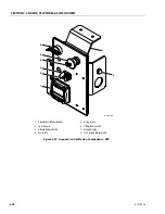
SIGNALS AND CONTROL CONNECTOR
NOTE:
Pin numbers 1, 5, 6, 9, 10, and 14 are labeled on the
connector’s inside face, next to the pins. On the mat-
ing plug, the same pin numbers are embossed on the
top of the body. The recommended wire thickness for
all pins is 16-20 AWG (0.50-1.00 mm
2
), 300V rated
(UL3266 or equivalent).
Wire colors listed are suggestions only.
Figure 3-62. Sample AMP Seal Connector and Pinout
Table 3-13. IC650 – DC Output
Wire Color
Pin
Description
Detail
White/Black
1
CAN GND
Isolated reference ground for
CAN signals. See Design Guide.
Blue
2
Interlock-NC
Dry Contact Interlock relay:
Normally closed contact.
Purple
3
Interlock-Common
Dry Contact Interlock relay:
Common contact.
Pink
4
Interlock-NO
Dry Contact Interlock relay:
Normally open contact.
White/Red
5
Battery temperature
sense +ve
Orange
6
CAN High
Isolated CAN high signal.
Black
7
Signal Ground
Do not connect to Battery Neg-
ative. Can be used with Pin 9.
Brown
8
Not used
Yellow
9
IC650: unused
IC900/IC1200: APO
IC650: Pin is unused IC900/
IC1200: Accessory Power Out-
put (+5VDC, 250 mA max)
White/
Orange
10
CAN Low
Isolated CAN Low.
Grey
11
Not used
Green
12
Remote LED Green
+ve
For Remote LED. Pin 12 goes
high with respect to Pin 13 to
light the Remote LED green,
and vice versa to light the
Remote LED red.
Red
13
Remote LED Red +ve
White
14
Battery temperature
sense -ve
Table 3-13. IC650 – DC Output
Wire Color
Pin
Description
Detail
Summary of Contents for ERT2669
Page 2: ......
Page 4: ...INTRODUCTION A 2 31215923 REVISON LOG Original Issue A January 08 2021...
Page 12: ...viii 31215923 TABLE OF CONTENTS...
Page 40: ...SECTION 1 SPECIFICATIONS 1 22 31215923...
Page 58: ...SECTION 2 GENERAL 2 18 31215923...
Page 187: ...SECTION 4 BASIC HYDRAULIC INFORMATION SCHEMATICS 31215923 4 11...
Page 206: ...SECTION 4 BASIC HYDRAULIC INFORMATION SCHEMATICS 4 30 31215923...
Page 225: ...SECTION 4 BASIC HYDRAULIC INFORMATION SCHEMATICS 31215923 4 49...
Page 242: ...SECTION 4 BASIC HYDRAULIC INFORMATION SCHEMATICS 4 66 31215923...
Page 307: ...SECTION 5 JLG CONTROL SYSTEM 31215923 5 65...
Page 334: ...SECTION 6 LSS SETUP CALIBRATION SERVICE 6 12 31215923...
Page 362: ...SECTION 7 GENERAL ELECTRICAL INFORMATION SCHEMATICS 7 28 31215923...
Page 374: ...SECTION 7 GENERAL ELECTRICAL INFORMATION SCHEMATICS 7 40 31215923...
Page 375: ......


