SECTION 3 - CHASSIS & TURNTABLE
3121160
3-213
15.
Allow all air to vent to atmosphere, then check compres-
sor oil level - top up if necessary. Check and correct any
leaks, tighten any loose fittings, check drive belt tension.
Normal Startup Procedure
1.
Check compressor oil level - top up if necessary.
2.
Air service valve (beside the compressor) closed.
3.
Start the engine.
4.
Compressor switch (in the platform) ON - compressor
should activate.
5.
Allow the compressor to warm up for several minute
before operating.
Normal Shutdown Procedure
1.
Close service valve and allow compressor to unload and
cool down (approx. 5 min.).
2.
Position the compressor switch in the platform to OFF.
3.
Shut down the engine.
Daily Operation
Before Starting:
1.
Check compressor oil level.
2.
Check for any leaks or loose bolts.
3.
Check drive belt is tight.
After Starting:
1.
Check pressure gauge for correct operating pressure.
2.
Check for leaks.
General Maintenance
A good maintenance program is the key to long compressor
life. Below is a program that when adhered to, should keep the
compressor in top operating condition. However, it should be
understood that these intervals are for normal operation in a
good clean environment. More frequent inspections, oil
changes and general maintenance should be carried out in
dusty environments, high ambient temperatures or extended
light load conditions.
DO NOT REMOVE CAPS, PLUGS OR ANY COMPONENTS WHEN THE COMPRES-
SOR IS RUNNING OR PRESSURIZED. STOP THE COMPRESSOR AND RELIEVE ALL
INTERNAL PRESSURE BEFORE DOING SO.
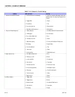
AFTER INITIAL 50 HOURS
1.
Change oil filter (Since initial oil filter will have collected
any foreign materials which have collected in manufac-
ture).
2.
Check belt tension and alignment (majority of belt
stretch will occur during early operation hours, also be
sure to check alignment).
3.
Check compressor oil for water or emulsion.
EVERY 500 HOURS (OR 6 MONTHS)
1.
Change compressor oil and filter.
2.
Change air filter (shorter intervals may be required if
dirty environment).
3.
Check belt tension and alignment.
4.
Blow out compressor cooler core.
5.
Check all fittings and fastenings.
6.
Test shutdown system.
EVERY 1000 HOURS (OR 1 YEAR)
1.
Check safety circuit switches.
2.
Check sump safety valve.
3.
Replace spin-on coalescer (sooner if required).
Summary of Contents for 740AJ
Page 2: ......
Page 55: ...SECTION 3 CHASSIS TURNTABLE 3121160 3 3 This page left blank intentionally...
Page 116: ...SECTION 3 CHASSIS TURNTABLE 3 64 3121160 Figure 3 44 Swing Hub Prior to SN 0300074383...
Page 203: ...SECTION 3 CHASSIS TURNTABLE 3121160 3 151 Figure 3 77 EFI Component Location...
Page 206: ...SECTION 3 CHASSIS TURNTABLE 3 154 3121160 Figure 3 78 ECM EPM Identification ECM EPM...
Page 224: ...SECTION 3 CHASSIS TURNTABLE 3 172 3121160 Figure 3 83 Deutz EMR 2 Troubleshooting Flow Chart...
Page 228: ...SECTION 3 CHASSIS TURNTABLE 3 176 3121160 Figure 3 87 EMR 2 Engine Plug Pin Identification...
Page 229: ...SECTION 3 CHASSIS TURNTABLE 3121160 3 177 Figure 3 88 EMR 2 Vehicle Plug Pin Identification...
Page 230: ...SECTION 3 CHASSIS TURNTABLE 3 178 3121160 Figure 3 89 EMR2 Fault Codes Sheet 1 of 5...
Page 231: ...SECTION 3 CHASSIS TURNTABLE 3121160 3 179 Figure 3 90 EMR2 Fault Codes Sheet 2 of 5...
Page 232: ...SECTION 3 CHASSIS TURNTABLE 3 180 3121160 Figure 3 91 EMR2 Fault Codes Sheet 3 of 5...
Page 233: ...SECTION 3 CHASSIS TURNTABLE 3121160 3 181 Figure 3 92 EMR2 Fault Codes Sheet 4 of 5...
Page 234: ...SECTION 3 CHASSIS TURNTABLE 3 182 3121160 Figure 3 93 EMR2 Fault Codes Sheet 5 of 5...
Page 303: ...SECTION 4 BOOM PLATFORM 3121160 4 31 Figure 4 20 Rotator Assembly HELAC...
Page 460: ...SECTION 5 BASIC HYDRAULIC INFORMATION AND SCHEMATICS 5 116 3121160 NOTES...
Page 467: ...SECTION 6 JLG CONTROL SYSTEM 3121160 6 7 Figure 6 2 ADE Block Diagram...
Page 534: ...SECTION 6 JLG CONTROL SYSTEM 6 74 3121160 NOTES...
Page 580: ...SECTION 7 BASIC ELECTRICAL INFORMATION SCHEMATICS 7 46 3121160 NOTES...
Page 581: ......

