


SECTION 3 - CHASSIS & TURNTABLE
3-44
– JLG Lift –
3121290
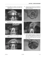
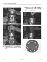
Removal
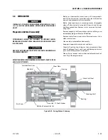
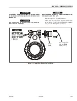
Refer to Figure 3-40., Swing Motor Removal and Installation.
1.
Thoroughly clean area around swing motor to prevent
dirt from entering system.
2.
Tag and disconnect hydraulic lines to swing motor. Cap
or plug all openings.
3.
Secure worm gear shaft so it does not pull out any when
removing swing motor. Failure to do so could damage
worm gear seals.
4.
Remove bolts securing swing motor to swing drive
assembly.
5.
Carefully pull the swing motor from the swing drive.
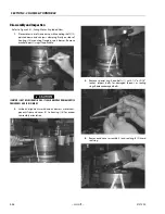
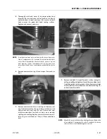
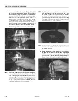
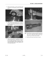
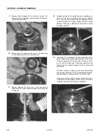
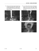
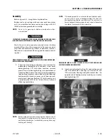
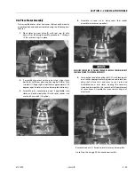
Preparation Before Disassembly
• Read this entire section before you disassemble motor or
any of its components for important information on parts
and procedures.
• Thoroughly clean off outside dirt, especially around fittings
and hose connections, before disconnecting and removing
motor. Remove rust or corrosion from coupling shaft.
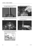
• Remove coupling shaft connections and hose fittings and
immediately plug port holes and fluid lines.
• Remove motor, drain fluids, and take it to a clean work sur-
face.
• Clean and dry motor before disassembly.
• As you disassemble motor, clean all parts except seals in
clean petroleum-based solvent and blow them dry.
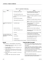
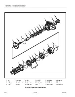
Table 3-11. Swing Motor Troubleshooting
Trouble
Cause
Remedy
Oil Leakage
1.
Hose fittings loose, worn or damaged.
2.
Oil seal rings (4) deteriorated by excess heat.
3.
Special bolt (1, 1 A, 1B or 1C) loose or its sealing area deterio-
rated by corrosion.
4.
Internal shaft seal (16) worn or damaged.
5.
Worn coupling shaft (12) and internal seal (16).
Check & replace damaged fittings or “O” Rings.
Torque to manufacturers specifications.
Replace oil seal rings by disassembling unit.
(a) Loosen then tighten single bolt to torque spec-
ification.
(b) Replace bolt.
Replace seal. Disassembly of motor unit necessary.
Replace coupling shaft and seal by disassembling
unit.
Significant loss of speed under
load
1.
Lack of sufficient oil supply
2.
High internal motor leakage
3.
Severely worn or damaged internal splines.
4.
Excessive heat.
(a) Check for faulty relief valve and adjust or
replace as required.
(b) Check for and repair worn pump.
(c) Check for and use correct oil for temperature of
operation.
Replace worn rotor set by disassembling unit.
Replace rotor set, drive link and coupling shaft by
disassembling unit.
Locate excessive heat source (usually a restriction)
in the system and correct the condition.
Low mechanical efficiency or
undue high pressure required to
operate unit
1.
Line blockage
2.
Internal interference
3.
Lack of pumping pressure
4.
Excessive binding or loading in system external to motor unit.
Locate blockage source and repair or replace.
Disassemble unit, identify and remedy cause and
repair, replacing parts as necessary.
Check for and repair worn pump.
Locate source and eliminate cause.
Summary of Contents for 450A II Series
Page 46: ...SECTION 3 CHASSIS TURNTABLE 3 6 JLG Lift 3121290 Figure 3 4 Drive Hub 4WD Front Only ...
Page 79: ...SECTION 3 CHASSIS TURNTABLE 3121290 JLG Lift 3 39 Figure 3 32 Swing Bearing Drive ...
Page 101: ...SECTION 3 CHASSIS TURNTABLE 3121290 JLG Lift 3 61 Figure 3 42 Auxiliary Pump ...
Page 113: ...SECTION 3 CHASSIS TURNTABLE 3121290 JLG Lift 3 73 Figure 3 53 EMR2 Fault Codes Sheet 1 of 5 ...
Page 114: ...SECTION 3 CHASSIS TURNTABLE 3 74 JLG Lift 3121290 Figure 3 54 EMR2 Fault Codes Sheet 2 of 5 ...
Page 115: ...SECTION 3 CHASSIS TURNTABLE 3121290 JLG Lift 3 75 Figure 3 55 EMR2 Fault Codes Sheet 3 of 5 ...
Page 116: ...SECTION 3 CHASSIS TURNTABLE 3 76 JLG Lift 3121290 Figure 3 56 EMR2 Fault Codes Sheet 4 of 5 ...
Page 117: ...SECTION 3 CHASSIS TURNTABLE 3121290 JLG Lift 3 77 Figure 3 57 EMR2 Fault Codes Sheet 5 of 5 ...
Page 159: ...SECTION 3 CHASSIS TURNTABLE 3121290 JLG Lift 3 119 ...
Page 161: ...SECTION 3 CHASSIS TURNTABLE 3121290 JLG Lift 3 121 ...
Page 163: ...SECTION 3 CHASSIS TURNTABLE 3121290 JLG Lift 3 123 ...
Page 165: ...SECTION 3 CHASSIS TURNTABLE 3121290 JLG Lift 3 125 ...
Page 173: ...SECTION 3 CHASSIS TURNTABLE 3121290 JLG Lift 3 133 Sensor Transducer Type ...
Page 177: ...SECTION 3 CHASSIS TURNTABLE 3121290 JLG Lift 3 137 Sensor Transducer Type ...
Page 179: ...SECTION 3 CHASSIS TURNTABLE 3121290 JLG Lift 3 139 ...
Page 181: ...SECTION 3 CHASSIS TURNTABLE 3121290 JLG Lift 3 141 ...
Page 183: ...SECTION 3 CHASSIS TURNTABLE 3121290 JLG Lift 3 143 ...
Page 185: ...SECTION 3 CHASSIS TURNTABLE 3121290 JLG Lift 3 145 ...
Page 187: ...SECTION 3 CHASSIS TURNTABLE 3121290 JLG Lift 3 147 ...
Page 203: ...SECTION 3 CHASSIS TURNTABLE 3121290 JLG Lift 3 163 ...
Page 207: ...SECTION 3 CHASSIS TURNTABLE 3121290 JLG Lift 3 167 ...
Page 217: ...SECTION 4 BOOM PLATFORM 3121290 JLG Lift 4 5 Figure 4 2 Boom Limit Switches ...
Page 310: ...SECTION 5 HYDRAULICS 5 70 JLG Lift 3121290 NOTES ...
Page 312: ...SECTION 6 JLG CONTROL SYSTEM 6 2 JLG Lift 3121290 Figure 6 2 Controller Block Diagram 0 ...
Page 370: ...SECTION 6 JLG CONTROL SYSTEM 6 60 JLG Lift 3121290 NOTES ...
Page 394: ...SECTION 7 BASIC ELECTRICAL INFORMATION SCHEMATICS 7 24 JLG Lift 3121290 NOTES ...
Page 395: ......