SECTION 3 - CHASSIS & TURNTABLE
3-8
– JLG Lift –
3121290
MAIN DISASSEMBLY for “B” Drives
1.
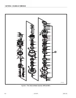
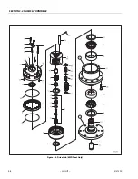
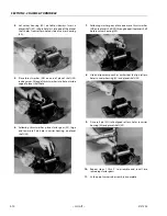
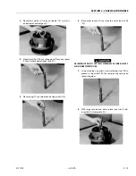
Turn hub (1G) on side, Remove coupling (14) from wide
end of spindle (1A).
2.
Mark location of shoulder bolt holes on outside of ring
gear and hub for easy realignment when rebuilding.
Remove four shoulder bolts (13) and 12 bolts (12) from
cover (6).
3.
Remove 16 flat washers (16) from cover (6).
4.
Lift cover sub-assembly (6) off ring gear (4). Set cover on
table with interior side facing up.
SHARP EDGES CAN CUT AND CAUSE SERIOUS INJURY. BEWARE OF SHARP
EDGES IN COUNTERBORE WHEN REMOVING O-RING.
5.
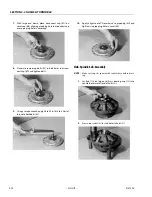
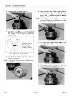
Remove O-ring (5) from counterbore around edge of
cover (6A). Discard O-ring.
NOTE:
If O-ring is not in cover counter- bore, it is in ring gear coun-
terbore. Remove it from hub and discard.
6.
Remove
thrust washer (11) from counter- bore in top of
carrier (3A).
7.
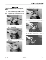
Remove input gear (8) from middle of carrier sub-assem-
bly (3).
8.
Lift ring gear (4) off hub (1G).
9.
Lift carrier sub-assembly (3) out of hub (1G).
10.
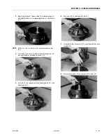
Remove thrust spacer (9) from input shaft (7) in middle
of spindle (1A).
11.
Lift input shaft sub-assembly (7) out of middle of spindle
(1A). Stand input shaft (7A) on splined end.
UNCONTROLLED OBJECTS CAN CAUSE EYE DAMAGE OR SERIOUS INJURY.
ALWAYS WEAR EYE PROTECTION.
12.
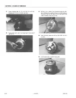
Using retaining ring pliers, remove retaining ring (7B)
from groove on input shaft (7A).
13.
Remove one spacer (7D), one spring (7C), and other
spacer (7D) from input shaft (7A).
14.
Remove
thrust washer (11) from around spindle (1A).
15.
Lift internal gear (2) out of hub (1G).
16.
Remove O-ring (5) from counterbore in hub (1G). Dis-
card O-ring.
17.
Main disassembly for ”B” drives is complete.
Hub-Spindle Disassembly
NOTE:
Start with large end of hub facing up and large end of spin-
dle facing down.
UNCONTROLLED OBJECTS CAN CAUSE EYE DAMAGE OR SERIOUS INJURY.
ALWAYS WEAR EYE PROTECTION.
1.
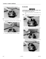
Remove retaining ring (1I) from around spindle (1A) ia
hub (1G).
2.
Remove
spacer (1H) from around spindle (1A) in hub
(1G).
3.
Set
hub (1G), with small end/spindle facing down, on
something that will support the hub’s flange while it lifts
hub up so spindle is not resting on anything. Carefully
press or hammer spindle (1A) down and out of hub (1G).
NOTE:
If seal (1B) and bearing cone (1D) come out of hub and rest
on spindle, remove these parts from spindle and set them
aside. Discard seal.
4.
If seal and bearing cone did not come out of small end
of hub (1G) when you pressed spindle out of hub,
remove seal (1B) and bearing cone (1D) from small end
of hub (1G). Discard seal.
5.
Bearing cone (1F) should be lying loose in wide end of
hub (1G). Remove bearing cone (1F) from inside hub
(1G).
NOTE:
Do not strike counterbore with punch if using a punch and
hammer when removing bearing cup.
6.
Remove bearing cup (1C) from counterbore in small end
of hub (1G).
NOTE:
Do not strike counterbore with punch if using a punch and
hammer when removing bearing cup.
7.
Turn hub (1G) over and lift it out of flange-support.
Remove bearing cup (1E) from counterbore in wide end
of hub (1G).
8.
Turn hub (1G) over onto its small end. Remove two pipe
plugs (1J) from side of hub (1G).
NOTE:
If your unit does not have studs, skip this step.
9.
Press nine studs (1N) out of stud holes in hub (1G).
10.
Hub-spindle disassembly is complete.
Summary of Contents for 450A II Series
Page 46: ...SECTION 3 CHASSIS TURNTABLE 3 6 JLG Lift 3121290 Figure 3 4 Drive Hub 4WD Front Only ...
Page 79: ...SECTION 3 CHASSIS TURNTABLE 3121290 JLG Lift 3 39 Figure 3 32 Swing Bearing Drive ...
Page 101: ...SECTION 3 CHASSIS TURNTABLE 3121290 JLG Lift 3 61 Figure 3 42 Auxiliary Pump ...
Page 113: ...SECTION 3 CHASSIS TURNTABLE 3121290 JLG Lift 3 73 Figure 3 53 EMR2 Fault Codes Sheet 1 of 5 ...
Page 114: ...SECTION 3 CHASSIS TURNTABLE 3 74 JLG Lift 3121290 Figure 3 54 EMR2 Fault Codes Sheet 2 of 5 ...
Page 115: ...SECTION 3 CHASSIS TURNTABLE 3121290 JLG Lift 3 75 Figure 3 55 EMR2 Fault Codes Sheet 3 of 5 ...
Page 116: ...SECTION 3 CHASSIS TURNTABLE 3 76 JLG Lift 3121290 Figure 3 56 EMR2 Fault Codes Sheet 4 of 5 ...
Page 117: ...SECTION 3 CHASSIS TURNTABLE 3121290 JLG Lift 3 77 Figure 3 57 EMR2 Fault Codes Sheet 5 of 5 ...
Page 159: ...SECTION 3 CHASSIS TURNTABLE 3121290 JLG Lift 3 119 ...
Page 161: ...SECTION 3 CHASSIS TURNTABLE 3121290 JLG Lift 3 121 ...
Page 163: ...SECTION 3 CHASSIS TURNTABLE 3121290 JLG Lift 3 123 ...
Page 165: ...SECTION 3 CHASSIS TURNTABLE 3121290 JLG Lift 3 125 ...
Page 173: ...SECTION 3 CHASSIS TURNTABLE 3121290 JLG Lift 3 133 Sensor Transducer Type ...
Page 177: ...SECTION 3 CHASSIS TURNTABLE 3121290 JLG Lift 3 137 Sensor Transducer Type ...
Page 179: ...SECTION 3 CHASSIS TURNTABLE 3121290 JLG Lift 3 139 ...
Page 181: ...SECTION 3 CHASSIS TURNTABLE 3121290 JLG Lift 3 141 ...
Page 183: ...SECTION 3 CHASSIS TURNTABLE 3121290 JLG Lift 3 143 ...
Page 185: ...SECTION 3 CHASSIS TURNTABLE 3121290 JLG Lift 3 145 ...
Page 187: ...SECTION 3 CHASSIS TURNTABLE 3121290 JLG Lift 3 147 ...
Page 203: ...SECTION 3 CHASSIS TURNTABLE 3121290 JLG Lift 3 163 ...
Page 207: ...SECTION 3 CHASSIS TURNTABLE 3121290 JLG Lift 3 167 ...
Page 217: ...SECTION 4 BOOM PLATFORM 3121290 JLG Lift 4 5 Figure 4 2 Boom Limit Switches ...
Page 310: ...SECTION 5 HYDRAULICS 5 70 JLG Lift 3121290 NOTES ...
Page 312: ...SECTION 6 JLG CONTROL SYSTEM 6 2 JLG Lift 3121290 Figure 6 2 Controller Block Diagram 0 ...
Page 370: ...SECTION 6 JLG CONTROL SYSTEM 6 60 JLG Lift 3121290 NOTES ...
Page 394: ...SECTION 7 BASIC ELECTRICAL INFORMATION SCHEMATICS 7 24 JLG Lift 3121290 NOTES ...
Page 395: ......

