

SECTION 3 - CHASSIS & TURNTABLE
3121290
– JLG Lift –
3-3
3.2
TORQUE HUB
Oil Information
1.
1. TYPE – EP90
Use EP90 for normal applications. For applications
where lubricant must meet special requirements, the
O.E.M can recommend a suitable substitute.
2.
OIL TEMPERATURE
Continuous – 160° F (70° C) Intermittent – 200° F (95° C).
3.
OIL CHANGE
Initial – After 50 hours or 50,000 revolutions of opera-
tion. Subsequent – After 1000 hours or (1) year, which-
ever comes first.
NOTE:
Higher temperatures make it necessary to change oil more
frequently.
4.
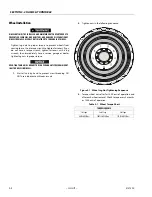
OIL FILL LEVEL AND VOLUME
Unit mounted horizontal – half full. (See Diagram A.)
Approximate volume - 17 oz. (0.5 1tr).
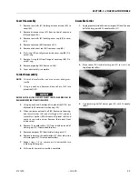
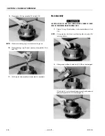
Roll and Leak Testing
Always roll and leak test Torque-Hubs after assembly to make
sure that the unit’s gears and sealants are working properly.
The following information briefly outlines what to look for
when performing these tests.
ROLL TEST
The roll test determines if the unit’s gears rotate freely and
properly. You should be able to rotate gears by applying a
con-
stant
force to the roll checker. If you feel
more
drag in gears
only at certain points, gears are not rolling freely. Examine
them for improper installation or defects.
Some gear packages roll with more difficulty than others. Do
not be concerned if gears seem to roll hard as long as they roll
with
consistency.
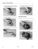
LEAK TEST
The purpose of a leak test is to make sure unit is air tight. You
can tell if your unit has a leak if pressure gauge test reading
starts to fall once you have pressurized the unit.
Leaks usually occur at the main seal or wherever O-rings or
gaskets are located. You can usually detect location of a leak
by brushing a soap and water solution around main seal and
where O-rings or gaskets meet unit exterior, then checking for
air bubbles. Replace part immediately if you detect a leak in a
seal, O-ring, or gasket.
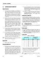
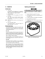
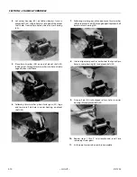
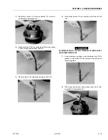
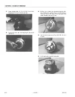
Tightening and Torquing Bolts
USE EXTREME CARE WHEN USING AN AIR IMPACT WRENCH. DO NOT TIGHTEN
BOLTS BEYOND THEIR TORQUE SPECIFICATION. NEVER USE AN IMPACT
WRENCH TO TIGHTEN SHOULDER BOLTS. TIGHTEN ALL SHOULDER BOLTS BY
HAND.
1.
Tighten (but do not torque) bolt ”A” until snug.
2.
Go to opposite side of bolt circle and tighten bolt ”B”
until equally snug.
3.
Continue around bolt circle and tighten remaining bolts.
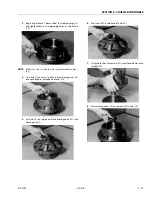
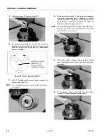
4.
Apply specified torque to bolt ”A”.
5.
Continue around bolt circle and apply equal torque to
remaining bolts.
Figure 3-2. Bolt Tightening Sequence
Summary of Contents for 450A II Series
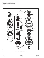
Page 46: ...SECTION 3 CHASSIS TURNTABLE 3 6 JLG Lift 3121290 Figure 3 4 Drive Hub 4WD Front Only ...
Page 79: ...SECTION 3 CHASSIS TURNTABLE 3121290 JLG Lift 3 39 Figure 3 32 Swing Bearing Drive ...
Page 101: ...SECTION 3 CHASSIS TURNTABLE 3121290 JLG Lift 3 61 Figure 3 42 Auxiliary Pump ...
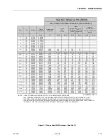
Page 113: ...SECTION 3 CHASSIS TURNTABLE 3121290 JLG Lift 3 73 Figure 3 53 EMR2 Fault Codes Sheet 1 of 5 ...
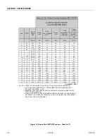
Page 114: ...SECTION 3 CHASSIS TURNTABLE 3 74 JLG Lift 3121290 Figure 3 54 EMR2 Fault Codes Sheet 2 of 5 ...
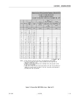
Page 115: ...SECTION 3 CHASSIS TURNTABLE 3121290 JLG Lift 3 75 Figure 3 55 EMR2 Fault Codes Sheet 3 of 5 ...
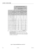
Page 116: ...SECTION 3 CHASSIS TURNTABLE 3 76 JLG Lift 3121290 Figure 3 56 EMR2 Fault Codes Sheet 4 of 5 ...
Page 117: ...SECTION 3 CHASSIS TURNTABLE 3121290 JLG Lift 3 77 Figure 3 57 EMR2 Fault Codes Sheet 5 of 5 ...
Page 159: ...SECTION 3 CHASSIS TURNTABLE 3121290 JLG Lift 3 119 ...
Page 161: ...SECTION 3 CHASSIS TURNTABLE 3121290 JLG Lift 3 121 ...
Page 163: ...SECTION 3 CHASSIS TURNTABLE 3121290 JLG Lift 3 123 ...
Page 165: ...SECTION 3 CHASSIS TURNTABLE 3121290 JLG Lift 3 125 ...
Page 173: ...SECTION 3 CHASSIS TURNTABLE 3121290 JLG Lift 3 133 Sensor Transducer Type ...
Page 177: ...SECTION 3 CHASSIS TURNTABLE 3121290 JLG Lift 3 137 Sensor Transducer Type ...
Page 179: ...SECTION 3 CHASSIS TURNTABLE 3121290 JLG Lift 3 139 ...
Page 181: ...SECTION 3 CHASSIS TURNTABLE 3121290 JLG Lift 3 141 ...
Page 183: ...SECTION 3 CHASSIS TURNTABLE 3121290 JLG Lift 3 143 ...
Page 185: ...SECTION 3 CHASSIS TURNTABLE 3121290 JLG Lift 3 145 ...
Page 187: ...SECTION 3 CHASSIS TURNTABLE 3121290 JLG Lift 3 147 ...
Page 203: ...SECTION 3 CHASSIS TURNTABLE 3121290 JLG Lift 3 163 ...
Page 207: ...SECTION 3 CHASSIS TURNTABLE 3121290 JLG Lift 3 167 ...
Page 217: ...SECTION 4 BOOM PLATFORM 3121290 JLG Lift 4 5 Figure 4 2 Boom Limit Switches ...
Page 310: ...SECTION 5 HYDRAULICS 5 70 JLG Lift 3121290 NOTES ...
Page 312: ...SECTION 6 JLG CONTROL SYSTEM 6 2 JLG Lift 3121290 Figure 6 2 Controller Block Diagram 0 ...
Page 370: ...SECTION 6 JLG CONTROL SYSTEM 6 60 JLG Lift 3121290 NOTES ...
Page 394: ...SECTION 7 BASIC ELECTRICAL INFORMATION SCHEMATICS 7 24 JLG Lift 3121290 NOTES ...
Page 395: ......


