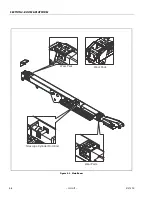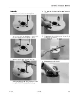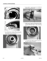
SECTION 4 - BOOM & PLATFORM
3121290
– JLG Lift –
4-7
4.2
ROTARY ACTUATOR
Theory of Operation
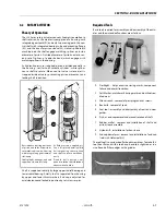
The L20 Series rotary actuator converts linear piston motion to
shaft rotation. Each actuator is composed of a housing with
integrated gear teeth (01) and only two moving parts: the cen-
tral shaft with integrated bearing tube and mounting flange
(02), and the annular piston sleeve (03). Helical spline teeth
machined on the shaft engage matching splines on inside
diameter of piston. Outside diameter of piston carries a sec-
ond set of splines, of opposite hand, which engage with
matching splines in the housing.
As hydraulic pressure is applied, piston is displaced axially in
the housing - similar to a hydraulic cylinder - while splines
cause shaft to rotate. When control valve is closed, oil is
trapped inside actuator, preventing piston movement and
locking shaft in position.
Shaft is supported radially by large upper radial bearing and
lower radial bearing. Axially, shaft is separated from housing
by upper and lower thrust washers. End cap is adjusted for
axial clearance and locked in position by set screws or pins.
Required Tools
Basic tools required for assembly and disassembly of the actu-
ator and their intended functions are as follows:
1.
Flashlight - helps examine timing marks, component
failure, and overall condition.
2.
Felt Marker - match mark timing marks and outline trou-
bled areas.
3.
Allen wrench - removal of port plugs and set screws.
4.
Box knife - removal of seals.
5.
Seal tool - assembly and disassembly of seals and wear
guides.
6.
Pry bar - end cap removal and manual rotation of shaft.
7.
Rubber mallet - removal and installation of shaft and
piston sleeve assembly.
8.
Nylon drift - installation of piston sleeve
9.
End cap dowel pins - removal and installation of end cap
(sold with Helac seal kit).
The seal tool is a customized flat-head screwdriver. To make this
tool, heat flat end with a torch and bend to a slight radius in a
vice. Round off sharp edges with a grinder.
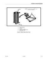
Bars indicate starting positions
of piston and shaft. Arrows indi-
cate rotation direction. Housing
with integral ring gear remains
stationary.
Shaft glands, bearings, and end
cap are not shown for clarity.
As fluid pressure is applied, pis-
ton is displaced axially while
helical gearing causes piston
and shaft to rotate simultane-
ously.
D o u b l e h e l i x d e s i g n c o m -
pounds rotation: shaft rotation is
about twice of piston.
Summary of Contents for 450A II Series
Page 46: ...SECTION 3 CHASSIS TURNTABLE 3 6 JLG Lift 3121290 Figure 3 4 Drive Hub 4WD Front Only ...
Page 79: ...SECTION 3 CHASSIS TURNTABLE 3121290 JLG Lift 3 39 Figure 3 32 Swing Bearing Drive ...
Page 101: ...SECTION 3 CHASSIS TURNTABLE 3121290 JLG Lift 3 61 Figure 3 42 Auxiliary Pump ...
Page 113: ...SECTION 3 CHASSIS TURNTABLE 3121290 JLG Lift 3 73 Figure 3 53 EMR2 Fault Codes Sheet 1 of 5 ...
Page 114: ...SECTION 3 CHASSIS TURNTABLE 3 74 JLG Lift 3121290 Figure 3 54 EMR2 Fault Codes Sheet 2 of 5 ...
Page 115: ...SECTION 3 CHASSIS TURNTABLE 3121290 JLG Lift 3 75 Figure 3 55 EMR2 Fault Codes Sheet 3 of 5 ...
Page 116: ...SECTION 3 CHASSIS TURNTABLE 3 76 JLG Lift 3121290 Figure 3 56 EMR2 Fault Codes Sheet 4 of 5 ...
Page 117: ...SECTION 3 CHASSIS TURNTABLE 3121290 JLG Lift 3 77 Figure 3 57 EMR2 Fault Codes Sheet 5 of 5 ...
Page 159: ...SECTION 3 CHASSIS TURNTABLE 3121290 JLG Lift 3 119 ...
Page 161: ...SECTION 3 CHASSIS TURNTABLE 3121290 JLG Lift 3 121 ...
Page 163: ...SECTION 3 CHASSIS TURNTABLE 3121290 JLG Lift 3 123 ...
Page 165: ...SECTION 3 CHASSIS TURNTABLE 3121290 JLG Lift 3 125 ...
Page 173: ...SECTION 3 CHASSIS TURNTABLE 3121290 JLG Lift 3 133 Sensor Transducer Type ...
Page 177: ...SECTION 3 CHASSIS TURNTABLE 3121290 JLG Lift 3 137 Sensor Transducer Type ...
Page 179: ...SECTION 3 CHASSIS TURNTABLE 3121290 JLG Lift 3 139 ...
Page 181: ...SECTION 3 CHASSIS TURNTABLE 3121290 JLG Lift 3 141 ...
Page 183: ...SECTION 3 CHASSIS TURNTABLE 3121290 JLG Lift 3 143 ...
Page 185: ...SECTION 3 CHASSIS TURNTABLE 3121290 JLG Lift 3 145 ...
Page 187: ...SECTION 3 CHASSIS TURNTABLE 3121290 JLG Lift 3 147 ...
Page 203: ...SECTION 3 CHASSIS TURNTABLE 3121290 JLG Lift 3 163 ...
Page 207: ...SECTION 3 CHASSIS TURNTABLE 3121290 JLG Lift 3 167 ...
Page 217: ...SECTION 4 BOOM PLATFORM 3121290 JLG Lift 4 5 Figure 4 2 Boom Limit Switches ...
Page 310: ...SECTION 5 HYDRAULICS 5 70 JLG Lift 3121290 NOTES ...
Page 312: ...SECTION 6 JLG CONTROL SYSTEM 6 2 JLG Lift 3121290 Figure 6 2 Controller Block Diagram 0 ...
Page 370: ...SECTION 6 JLG CONTROL SYSTEM 6 60 JLG Lift 3121290 NOTES ...
Page 394: ...SECTION 7 BASIC ELECTRICAL INFORMATION SCHEMATICS 7 24 JLG Lift 3121290 NOTES ...
Page 395: ......

