background image

SECTION 3 - TROUBLESHOOTING

31215808

3-9

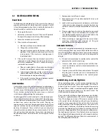
Figure 3-5.  Outrigger Socket Contactor Heads and Outrigger Beam - Contactor Plate Mounting Hardware

(ORIGINAL AND 5/2001 - DESIGN)

MAF32980

OUTRIGGER BEAM

JACK END OF 

OUTRIGGER BEAM

NYLON 

WASHERS

ACORN NUT

BRASS 

FLAT HEAD SCREW

APPLY LOW STRENGTH 

THREADLOCKING 

COMPOUND TO THREADS

INSULATOR 

BUSHING

CONTACTOR 

PLATE

O-RINGS

OUTRIGGER SOCKET 

(FLOOR)

OPEN END OF 

OUTRIGGER SOCKET

APPLY MEDIUM 

STRENGTH 

THREADLOCKING COMPOUND 

TO THREADS

NUT

NYLON WASHERS

INSULATOR BUSHING

ROUND HEAD SCREW

Go 

to 

Discount-Equipment.com 

to 

order 

your 

parts

Summary of Contents for 25AM

Page 1: ...Service and Maintenance Manual Models 25AM 30AM 38AM PVC 2002 31215808 February 25 2020 Rev A AS NZS G o t o D i s c o u n t E q u i p m e n t c o m t o o r d e r y o u r p a r t s...

Page 2: ...ith a quote for the right part that your machine needs We sell worldwide for the brands Genie Terex JLG MultiQuip Mikasa Essick Whiteman Mayco Toro Stone Diamond Products Generac Magnum Airman Haulott...

Page 3: ...AFETY It should be noted that the machine s hydraulic systems operate at extremely high potentially dangerous pres sures Every effort should be made to relieve any system pressure prior to disconnecti...

Page 4: ...INTRODUCTION A 2 31215808 REVISON LOG Original Issue A February 25 2020 G o t o D i s c o u n t E q u i p m e n t c o m t o o r d e r y o u r p a r t s...

Page 5: ...rt 1 7 Metric Fastener Torque Chart 1 13 SECTION 2 SERVICE PROCEDURES 2 1 Machine Preparation Inspection And Maintenance 2 1 General 2 1 Preparation Inspection and Maintenance 2 1 Pre Start Inspection...

Page 6: ...ressure Check Valve Installation 2 15 2 8 Hydraulic Lift Cylinder Removal Inspection and rebuild 2 16 Cylinder Removal 2 16 Cylinder Disassembly 2 16 Lift Cylinder Component Inspection 2 16 Cylinder A...

Page 7: ...cs 3 1 Grounding 3 1 Backprobing 3 1 Min Max 3 1 Polarity 3 2 Scale 3 2 Continuity Measurement Over Long Distances 3 2 Requirements 3 2 Procedure 3 2 3 5 Electrical Switch Testing 3 5 Basic Check 3 5...

Page 8: ...urement DC 3 3 3 2 Resistance Measurement 3 3 3 3 Continuity Measurement 3 4 3 4 Current Measurement DC 3 4 3 5 Outrigger Socket Contactor Heads and Outrigger Beam Contactor Plate Mounting Hardware OR...

Page 9: ...s for Various Components 1 3 2 1 Inspection and Maintenance 2 2 2 2 AM Model Preventive Maintenance Inspection Schedule 2 3 2 3 Chain Stretch Tolerance 2 6 2 4 AM Series Mast Component Features 2 20 3...

Page 10: ...vi 31215808 LIST OF TABLES TABLE NO TITLE PAGE NO G o t o D i s c o u n t E q u i p m e n t c o m t o o r d e r y o u r p a r t s...

Page 11: ...ith a quote for the right part that your machine needs We sell worldwide for the brands Genie Terex JLG MultiQuip Mikasa Essick Whiteman Mayco Toro Stone Diamond Products Generac Magnum Airman Haulott...

Page 12: ...75x72in 1 90x1 83m 86x84in 2 18x2 13m MachineBase Overall LengthxWidth 49x29in 1 24mx74cm 52x29in 1 32mx74cm 52x29in 1 32mx74cm 57 5x29in 1 46mx74cm MaximumWindSpeed 0mph 0kph Machineratedforindooruse...

Page 13: ...premium fluid Aside from JLG recommendations it is not advisable to mix oils of different brands or types as they may not contain the same required additives or be of comparable viscosities If use of...

Page 14: ...Check Hyd OilLevel HO Change Hyd Oil Checkoilleveleveryday Changehydraulicoilevery2years 2 SwivelRaceways 2 FrontCasters MPG PressureGun 3 LevelingJackScrews 4 JackThreads MPG Brush 4 MastChains 2 Per...

Page 15: ...FUNNEL MUST BE USED 1 10 HYDRAULIC PRESSURE ADJUSTMENT See Figure 1 2 Adjust system pressure so that platform will raise with rated capacity in platform Turning adjustment screw clockwise increases s...

Page 16: ...equivalent centimeters cm given in parentheses DESCRIPTION BORE in cm STROKE in cm ROD DIA in cm LiftCylinder 25AM 1 63 4 14 56 50 143 50 1 38 3 50 LiftCylinder 30AM 1 63 4 14 56 50 143 50 1 38 3 50 L...

Page 17: ...e substituted in place of Vibra TITE 121 JLG PN Loctite ND Industries Description 0100011 242 Vibra TITE 121 MediumStrength Blue 1001095650 243 Vibra TITE 122 MediumStrength Blue 0100019 271 Vibra TIT...

Page 18: ...99 10700 90 122 65 88 100 136 80 108 9 16 12 0 5625 0 1820 11600 110 149 80 108 120 163 98 133 18 0 5625 0 2030 12950 120 163 90 122 135 184 109 148 5 8 11 0 6250 0 2260 14400 150 203 110 149 165 224...

Page 19: ...165 110 150 90 120 9 16 12 0 5625 0 1820 16400 155 210 140 190 115 155 18 0 5625 0 2030 18250 170 230 155 210 130 175 5 8 11 0 6250 0 2260 20350 210 285 190 260 160 220 18 0 6250 0 2560 23000 240 325...

Page 20: ...20 0 5000 0 1599 10700 75 100 71 97 65 88 9 16 12 0 5625 0 1820 11600 90 120 87 118 80 109 18 0 5625 0 2030 12950 105 145 97 132 90 122 5 8 11 0 6250 0 2260 14400 130 175 120 163 115 156 18 0 6250 0...

Page 21: ...95 130 90 120 9 16 12 0 5625 0 1820 16400 130 175 125 170 115 155 18 0 5625 0 2030 18250 145 195 135 185 130 175 5 8 11 0 6250 0 2260 20350 180 245 170 230 160 220 18 0 6250 0 2560 23000 205 280 190...

Page 22: ...5 130 175 5 8 11 0 6250 0 2260 20350 180 245 170 230 160 220 18 0 6250 0 2560 23000 205 280 190 260 180 245 3 4 10 0 7500 0 3340 30100 320 435 300 415 280 380 16 0 7500 0 3730 33600 355 485 335 455 31...

Page 23: ...185 130 175 5 8 11 0 6250 0 2260 20350 180 245 170 230 160 220 18 0 6250 0 2560 23000 205 280 190 260 180 245 3 4 10 0 7500 0 3340 30100 320 435 300 415 280 380 16 0 7500 0 3730 33600 355 485 335 455...

Page 24: ...75 84 30 36 7 88 66 79 97 14 2 115 50 0 140 105 126 154 16 2 157 68 3 219 164 197 241 18 2 5 192 83 5 301 226 271 331 20 2 5 245 106 5 426 320 383 469 22 2 5 303 132 0 581 436 523 639 24 3 353 153 5 7...

Page 25: ...5 12 1 75 84 30 52 5 125 115 95 14 2 115 71 6 200 180 150 16 2 157 97 8 315 280 235 18 2 5 192 119 5 430 385 325 20 2 5 245 152 5 610 550 460 22 2 5 303 189 0 830 750 625 24 3 353 222 0 1065 960 800 2...

Page 26: ...5 2 43 40 38 12 1 75 84 30 36 7 75 70 66 14 2 115 50 0 119 110 105 16 2 157 68 3 186 175 165 18 2 5 192 83 5 256 240 225 20 2 5 245 106 5 362 340 320 22 2 5 303 132 0 494 465 435 24 3 353 153 5 627 59...

Page 27: ...58 55 12 1 75 84 30 52 5 105 100 95 14 2 115 71 6 170 160 150 16 2 157 97 8 265 250 235 18 2 5 192 119 5 365 345 325 20 2 5 245 152 5 520 490 460 22 2 5 303 189 0 705 665 625 24 3 353 222 0 905 850 80...

Page 28: ...ith a quote for the right part that your machine needs We sell worldwide for the brands Genie Terex JLG MultiQuip Mikasa Essick Whiteman Mayco Toro Stone Diamond Products Generac Magnum Airman Haulott...

Page 29: ...nspection shall be accomplished for each machine in service for 3 months or 150 hours whichever comes first out of service for a period of more than 3 months or when purchased used The frequency of th...

Page 30: ...ris 6 Decals installed and legible 7 Check for proper tolerances routing and lubrication 8 Fully Charged 9 Verify Perform Footnotes 1 Prior to each sale lease or delivery 2 In service for 3 months Out...

Page 31: ...OLS Controlsoperateproperlyreturntoneutral offwhenreleased 3 9 3 9 EmergencyStopSwitches GroundANDPlatform 3 3 TouchpadandLEDslightwhenpadsaredepressed 3 3 DriveLiftModeSelectorSwitch 3 3 ManualDescen...

Page 32: ...JLGofMachineOwnership 9 9 AnnualMachineInspectionDue 9 9 AllRelevantSafetyPublicationsIncorporated 9 9 AllDecals PlacardsInstalled Secure Legible 9 9 AllFasteners Pins Shields andCovers 1 2 1 2 Functi...

Page 33: ...at no adjacent parts are interfering Component Disassembly and Reassembly When disassembling or reassembling a component complete the procedural steps in sequence Do not partially disassemble or assem...

Page 34: ...Cracks Fatigue is a phenomenon that affects most metals and is the most common cause of chain plate failures Fatigue cracks are found through the link holes perpendicular 90 degrees from the pin in l...

Page 35: ...ds the use of ISO Vg grade 32 46 oil with a viscosity range between 15 250 SUS at 100 degrees F 32 54 cST at 40 degrees C Changing Hydraulic Oil Use of any of the recommended hydraulic oils eliminates...

Page 36: ...s which are available from the JLG Parts Department Transformer Printed Circuit Board Shunt Assembly Interlock Relay SCR Rectifier AC Circuit Breaker DC Circuit Breaker Replacement and troubleshooting...

Page 37: ...ransformer Printed Circuit Board Replacement 1 Disconnect the wide wiring connector from the end of the circuit board 2 Remove the four 4 screw attaching the card to the front face of the charger chas...

Page 38: ...sulator may need to be restrained to keep it from turning while removing the shunt assem bly fasteners Also make note of the position of each washer nut and wire connector when removing for later asse...

Page 39: ...which is holding boot to positive end of battery over battery cable 2 Remove nut from cap screw attaching battery cable to fuse 3 Replace the fuse 4 Follow reverse procedure for securing the fuse MAF...

Page 40: ...lips Soldered 5 Power Lead Clip Attach Screws REMOVE THE MOTOR COVER CAREFULLY THE SHORT POWER LEADS INSIDE THE COVER FROM THE POSTS ARE SOLDERED TO ATTACH CLIPS WHICH ARE FASTENED TO THE BRUSH CARRIE...

Page 41: ...Brush Carrier Position on Motor Housing 4 Brush Carrier Assembly NOTE a Removedpreviouslywithmotorcoverdisassembly shownforreferenceonly 1 2 3 4 Brush Assembly Remove Install 1 Brush Assembly a 2 Brus...

Page 42: ...ank Screws 4 4 Use Screwdriver to pry tank away from pump head Filter Screen Installation 1 Filter Screen 2 Pump Pick Up Tube 1 2 2 3 4 1 2 Pump Installation 1 Pump Assembly 3 Pump Shaft Seal 2 Pump A...

Page 43: ...Spring 6 Extend Pressure Port Shown Plugged Note AdjustpressureperspecificationshowninSection 1ofthisServiceManual 1 2 3 4 6 5 Pressure Check Valve Installation 1 Check Valve Assembly 5 Check Valve P...

Page 44: ...y damage to this surface will require replacement of the rod 2 Extend the rod until the piston bottoms out against the cylinder head 3 Compress the head retraining ring enough to allow the cylinder he...

Page 45: ...There should be no scratches or pits deep enough to catch the fin gernail Scratches that catch the fingernail but are less than 0 5 in long and primarily in the circumferential direction are acceptabl...

Page 46: ...g 9 O Ring 10 Seal 11 Seal Piston 12 Knob Red 13 Poppet SolenoidValve 14 Plug 15 FlowControlValve 16 Plug 17 Ring Wear Figure 2 2 Lift Cylinder Assembly 16 15 12 13 14 17 5 8 6 7 2 3 11 10 9 1 MAF3064...

Page 47: ...tep is easier done with two people one to slide the cylinder into the mast the other to guide the rod into the cylinder block at the top of the mast 3 Slide the cylinder into the mast and install the...

Page 48: ...all side to side section movement is eliminated but section can still slide in mast by hand Mast Disassembly Procedure See Figure 2 3 NOTE Reference to mast sections 6 7 made following is depen dent o...

Page 49: ...y NOTE Step 15 applies to removal of the cable assemblies used on mast section 5 15 While mast section 5 is still extended from section 4 remove the bolts attaching the two 2 cable assembly anchor eye...

Page 50: ...oles at top of mast 2 Locate the two 2 single wide chain assemblies Lay out each chain assembly with anchor block end towards mast and notched end of block down be certain floor surface is clean and f...

Page 51: ...25AM Mast Assembly Components 6 Section MAF30610H 0801297 H MAST SECTION 5 MAST SECTION 6 MAST SECTION 1 MAST SECTION 2 MAST SECTION 3 MAST SECTION 4 BRACKET LIFT CYLINDER G o t o D i s c o u n t E q...

Page 52: ...Mast Assembly Components 7 Section MAF30620I 0801298 I MAST SECTION 1 MAST SECTION 2 MAST SECTION 3 MAST SECTION 4 MAST SECTION 5 MAST SECTION 6 MAST SECTION 7 LIFT CYLINDER BRACKET G o t o D i s c o...

Page 53: ...2 6 Mast Chain Cable Routing Diagram SECTION 1 SECTION 2 SECTION 3 SECTION 4 SECTION 5 SECTION 6 SECTION 7 MAF30630 CHAIN ASSEMBLY HYDRAULIC CYLINDER LIFTS HERE BRACKETS G o t o D i s c o u n t E q u...

Page 54: ...d end and attach to mast section 2 using following steps a Insert sheave pin through anchor block on cylinder rod end b Place sheave wheels for wide chain on sheave pin one each side of anchor block c...

Page 55: ...e adjusted later in assembly 36 Insert chain adjustment into the top of mast section 4 by using spacer chain equalizer and Keeper Secure one end of the chain assembly with chain adjustment by using tw...

Page 56: ...ns 2 3 and 4 may need to be restrained to keep their slide pads from pushing out the bottom of mast sections 1 2 and 3 53 Insert slide pads into the top end mast rails between sec tion 4 and 5 one on...

Page 57: ...es use six 6 mast sections the 30 and 38 ft models use seven 7 mast sections 72 Locate the remaining mast section 6 7 platform mount ing mast section Lay mast section on flat stable surface 73 Attach...

Page 58: ...ction 5 6 until bottom ends of masts are even Check to make sure cable set attached to top of section 3 4 5 is seating properly in cable sheave wheels attached to top of mast section 4 5 6 Mast sectio...

Page 59: ...support cross member 7 Attach mast to base using four 4 3 8 in x 1 in long hex head bolts flatwashers and nuts place a flatwasher under bolt head mount with nuts on inside of frame Apply Medium Streng...

Page 60: ...e platform check the side profile of the top of the mast for the amount of adjustment nec essary to obtain the 7 16 in 11mm step for mast sec tions 3 and up See Figure 2 7 Figure 2 7 Mast Chain Cable...

Page 61: ...ment to service broken or worn sequence cables This kit consists of a replacement sequence cable with the threaded top end attached same as the top end of the fac tory cable Also included is a clamp d...

Page 62: ...ently forcing a screwdriver between the outer strands to unlay the cable When done properly the outer strands will form a symmetrical basket Do not straighten out the spiral lay of the strands unlay a...

Page 63: ...cable and retighten the socket fitting There is no specific requirement for torque 8 Inspect for proper assembly prior to loading the cable Strands visible through the inspection hole are your assuran...

Page 64: ...SS 1 CoilSpring 2 Capscrew 3 LockNut 4 Bolt 5 Nut 6 Capscrew 7 LockNut 8 Support Figure 2 8 Load Sensing System LSS 4 5 1 3 2 6 7 8 MAF30820A 1001255532 A SEE DETAIL A DETAIL A SECTION A A G o t o D i...

Page 65: ...crews will be loose Setting Positive Stops 3 Load platform with 120 rated load 4 For Bolt On Platform adjust capscrews 2 with 1 32 in to 1 16 in air gap between capscrews 6 head and angle on washer 8...

Page 66: ...SECTION 2 SERVICE PROCEDURES 2 38 31215808 G o t o D i s c o u n t E q u i p m e n t c o m t o o r d e r y o u r p a r t s...

Page 67: ...ith a quote for the right part that your machine needs We sell worldwide for the brands Genie Terex JLG MultiQuip Mikasa Essick Whiteman Mayco Toro Stone Diamond Products Generac Magnum Airman Haulott...

Page 68: ...nce for improper function of a hydraulic system where the cause is not immediately apparent should be the Hydraulic Diagram Circuit The best place to begin the prob lem analysis is at the power source...

Page 69: ...t a more accurate mea surement Consult the circuit schematic to determine which wires to use in addition to wire under test here called wire 1 and wire 2 and how to isolate these wires These wires sho...

Page 70: ...ntact with meter leads First test meter and leads by touching leads together Resistance should read a short circuit very low resis tance Circuit power must be turned OFF before testing resis tance Dis...

Page 71: ...cuit before testing Use firm contact with meter leads First test meter and leads by touching leads together Meter should produce an audible alarm indicating conti nuity Set up the meter for the expect...

Page 72: ...if it was disconnected for step 1 and turn on machine 3 Hold switch away from metal and observe switch state in the control system diagnostics using the Analyzer See vehicle or control system documen...

Page 73: ...areONandmotordoesnotstart Redemergencystopbuttonisengaged PUSHEDIN on eithergroundcontrolstationoronplatform Disengage TURNCLOCKWISE redemergencybutton untilitpopsout Controlrelaynotfunctioning Replac...

Page 74: ...sareONandmotordoesnotstart Redemergencybuttonisengaged PUSHEDIN on eithergroundcontrolstationoronplatform Disengage TURNCLOCKWISE redemergencybutton untilitpopsout Controlrelaynotfunctioning Replacec...

Page 75: ...e outrigger socket 4 Apply Medium Strength Threadlocking Compound to screw threads 5 Install one 1 standard 8 brass nut and thread in against nylon washer until insulating grommet just starts to compr...

Page 76: ...OUTRIGGER BEAM NYLON WASHERS ACORN NUT BRASS FLAT HEAD SCREW APPLY LOW STRENGTH THREADLOCKING COMPOUND TO THREADS INSULATOR BUSHING CONTACTOR PLATE O RINGS OUTRIGGER SOCKET FLOOR OPEN END OF OUTRIGGE...

Page 77: ...series of holes drilled around the CONTACTOR PLATE assembly OUTRIGGER SOCKETS are equipped with button head screws detent screws mounted around the CONTACTOR SCREW HEADS on the floor of the outrigger...

Page 78: ...SECTION 3 TROUBLESHOOTING 31215808 3 11 G o t o D i s c o u n t E q u i p m e n t c o m t o o r d e r y o u r p a r t s...

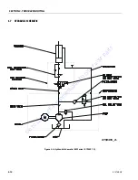
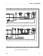
Page 79: ...CTION 3 TROUBLESHOOTING 3 12 31215808 3 7 HYDRAULIC SCHEMATIC 2792491_A Figure 3 6 Hydraulic Schematic AM Series 2792491_A G o t o D i s c o u n t E q u i p m e n t c o m t o o r d e r y o u r p a r t...

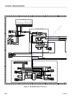
Page 80: ...E HARNESS 12 3 WIRE HARNESS 16 5 SHEET 4 AC POWER UNIT 100VAC 240VAC TRANS FORMER HARNESS 100VAC HARNESS 240VAC HARNESS AC PLUG SHEET 5 MAST CABLES 25AM 30AM 38AM CABLE RETRACTILE 16 5 CABLE 16 5 DC C...

Page 81: ...3 1 RL06 4 1 RL06 2 1 RL06 7 1 RL06 6 1 RL06 1 1 YEL YEL T126 1 T127 1 T128 1 T129 1 YEL 1 YEL 1 YEL 2 YEL 2 YEL 3 YEL 3 YEL 4 YEL 4 T130 1 T133 1 T134 1 T135 1 O R LED TO O R CONTACTOR TO O R CONTAC...

Page 82: ...EC4 1 EC4 B 1 BLK BLK BLK BLK T400 1 RED 3 RED 3 LIFT DOWN VALVE HV927 1 1 HV927 2 1 LIFT UP VALVE HV925 1 1 HV925 2 1 GRN 4 GRN 4 BLU 1 BLU 1 RED 1 RED 1 T399 1 BLK 4 BLK 4 ORG 2 ORG 2 ORG 1 ORG 1 T...

Page 83: ...09 4 1 WHT 8 WHT 8 T210 5 1 T211 AC 1 BLK 7 BLK 7 T212 6 1 BLK 9 BLK 9 T213 8 1 WHT 9 WHT 9 T214 5 1 T215 1 1 BLK 5 BLK 5 T216 2 1 BLK 8 BLK 8 BLK 4 T217 1 1 T217 7 1 BLK T221 7 1 GRN GRN WHT S225 S22...

Page 84: ...12 AWG BLK 6 12 AWG BLK 6 EC4 GND 1 X609 1 2 GRN 2 GRN 2 BLK 1 GRN 3 GRN 3 YEL 3 YEL 3 S190 S191 S192 YEL 1 T1218 7C 1 GRN 12 GRN 12 12AWG WHT 12 12AWG WHT 12 12AWG BLK 12 12AWG BLK 12 GRN 8 WHT 2 T20...

Page 85: ...290 0 1 T291 AC 1 WHT 5 WHT 5 T292 2 1 RED 3 IP293 5A T294 DC 1 BLK BLK T295 1 1 BLK BLK T296 2 1 T297 AC 1 BLK 7 BLK 7 T298 6 1 WHT 4 T299 9 1 WHT 6 WHT 6 T300 5 1 BLK 4 T301 10 1 BLK 5 BLK 5 TERMINA...

Page 86: ...CUIT BREAKER 15A CB258 1 1 CB258 2 1 WHT 10 WHT 10 WHT 7 WHT 7 WHT 4 WHT 3 WHT 3 BLK 3 BLK 3 BLK 4 IP265 5A 1 BLK BLK CIRCUIT BREAKER 15A CB275 1 1 CB275 2 1 WHT WHT BLK BLK 1 GRN GRN GROUND STUD T283...

Page 87: ...RED GRN GRN BLK WHT BLK WHT BRN BRN BLU BLU GRN YEL GRN YEL T326 1 T327 1 T328 1 T330 1 T331 1 T332 1 T333 1 BLK BLK WHT WHT RED RED GRN GRN BLK WHT BLK WHT BRN BRN BLU BLU GRN YEL GRN YEL T334 1 T335...

Page 88: ...SECTION 3 TROUBLESHOOTING 31215808 3 21 G o t o D i s c o u n t E q u i p m e n t c o m t o o r d e r y o u r p a r t s...

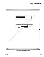
Page 89: ...GRN ORG ORG GENERIC AH342 1 AH342 1 T343 1 T344 1 BLK BLK BLU ORN BLU ORN AH342 B 1 AH342 B 1 HOUR METER TO LIFT UP VALVE HV925 TO LIFT DOWN VALVE DECENT ALARM 1000uF 25V GENERIC Figure 3 15 Electric...

Page 90: ...BLK BLK RL06 1B 1 RL06 7B 1 YEL YEL GRN GRN CO346 1 2 3 1 2 3 T348 1 T349 1 S350 RED RED BLK BLK GRN GRN STROBE LIGHT TO POTTED RELAY SHEET 2 A3 SECURITY LOCK OPTION TO GROUND CONTROL BOX SECURITY LO...

Page 91: ...SECTION 3 TROUBLESHOOTING 3 24 31215808 G o t o D i s c o u n t E q u i p m e n t c o m t o o r d e r y o u r p a r t s...

Page 92: ...ith a quote for the right part that your machine needs We sell worldwide for the brands Genie Terex JLG MultiQuip Mikasa Essick Whiteman Mayco Toro Stone Diamond Products Generac Magnum Airman Haulott...

Page 93: ...G o t o D i s c o u n t E q u i p m e n t c o m t o o r d e r y o u r p a r t s...

Reviews: