SECTION 3 - CHASSIS & SCISSOR ARMS
3121273
– JLG Lift –
3-23
ture (2) will be attached to the commutator end
head.
9. Pull back the Brush Springs (4) in the commutator
end head, pull the brush back and rest the springs
on the side of the brush. The brushes should move
freely within the holders.
10. Use an arbor press or a bearing puller to remove the
armature from the commutator end head assembly.
11. Remove the Snap Ring (7) and Bearing (8) from the
commutator end head. Discard the bearing.
Drive Motor Inspection and Service
NOTE:
Refer to Figure 3-24.
1. Carefully blow out any accumulated carbon dust
and dirt from the Commutator End Head (9) and the
Frame & Field Assembly (2) using clean, oil free,
compressed air.
2. Replace Brushes (5) that are worn below their
usable length of 0.6 in (1.5 cm), show signs of
uneven wear or signs of overheating, such as discol-
ored brush shunts and brush springs. Brushes
should always be replaced in complete sets of four.
Use identical replacement parts; do not substitute
brush grades as the brushes are matched to the
motor type and application to provide the best ser-
vice. Substituting brushes of the wrong grade can
cause premature commutator failure and excessive
brush wear.
3. Make sure the Brush Box Assembly (6) is tight on
the commutator end head. Replace brush box
assemblies in the commutator end head if they are
physically damaged or brush holders are loose on
the brush plate.
4. Visually inspect the frame and field assembly for
overheating or other signs of damage. Check all wir-
ing to ensure that the insulation is in good condition.
Verify that pole screws are torqued to 250 - 300 in-lb
(28.2 - 33.9 Nm). Verify field resistance using a suit-
able ohmmeter per the appropriate motor specifica-
tion. Verify that the field is electrically isolated from
the frame using a dielectric tester. Replace as neces-
sary.
5. Visually inspect the Armature Assembly (3) for signs
of overheating or physical damage. Visually inspect
the seal surface of the shaft for excessive wear.
Check for grounded circuits using a dielectric tester
by applying voltage between the commutator and
the shaft. Visually inspect the commutator for exces-
sive wear and overheating. Replace as necessary.
6. Visually inspect the brake surfaces for excessive
wear. Replace Brake Assembly (11) if necessary.
7. Visually inspect the Wire Harness (1) for frayed insu-
lation, loose terminals, or other damage. Replace as
necessary.
Drive Motor Reassembly
NOTE:
Refer to Figure 3-24.
1. After inspection and servicing, reassemble the wir-
ing in the Commutator End Head (9) as originally
found. Ensure the wiring does not contact metal
parts and that it allows the brushes to move unre-
stricted in the holders. Motor terminals must be
assembled as shown Figure 3-26. Torque bottom
terminal nut to 110 - 140 in-lb (12.4 - 15.8 Nm).
2. After the motor has been disassembled, it is recom-
mended that new bearings be installed because
bearings may have been damaged during removal.
Although the bearings may appear and feel good,
the bearing races could be “brinelled” (races or balls
deformed) and may exhibit noise and vibration prob-
lems or fail within a relatively short period of service.
Press a new bearing into the commutator end head,
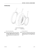
pressing on the outer race only. See Figure 3-25..
Replace the Retaining Ring (7) in the retaining ring
groove.
3. Press the Armature (3) commutator end into the
commutator end head and bearing assembly, care-
fully supporting the inner-race of the bearing. See
Figure 3-25.
4. Carefully release the Brush Springs (4) allowing the
Brushes (5) to contact the commutator. Make sure
brush shunts do not interfere with spring movement.
5. Assemble the commutator end head to the Frame &
Field Assembly (2) and tighten the screws to 120 -
140 in-lb (13.6 - 15.8 Nm). Make sure to align the
field connection with the notch in the commutator
end head. Seal wires where they exit from commuta-
tor end head with the Grommet (10).
6. Place the Gasket Seal (12) in the bottom of the
notch in the commutator end head. Align wires from
the Brake Assembly (11) into the notch in the com-
mutator end head. Secure brake assembly to com-
mutator end head using three bolts.
7. Install Wire Harness (1) to motor by connecting the
brake connectors and securing the armature termi-
nals to the terminal studs. Crimp the field connection
(red/orange to orange and blue to blue) together
and heat shrink. Motor terminals must be assembled
as shown in
Always secure the bottom nut with a
wrench as you tighten the top nut.
Torque top nut
to 90 - 110 in-lb (10.2 - 12.4 Nm).


