


SECTION 6 - MAST COMPONENTS
3121222
– JLG Lift –
6-7
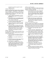
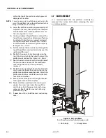
Mast Removal
NOTE:
To ease removal and installation of the mast assem-
bly it is recommended that the complete machine
be elevated on suitable stands to allow easy access
to the mounting bolts on the base of the mast
assembly.
1.
Lower the mast assembly completely before
beginning the mast removal process to ensure
no residual pressure remains in the lift cylinder.
2.
Attach an overhead crane by strap through the
cross supports on the top of mast sections.
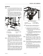
3.
Remove the four (4) bolts, nuts, washers, and
shims from the base mount of the mast. Access
the bolts and nuts through the access holes in
the bottom and front of the base frame.
NOTE:
Before removing the mast off the machine, you
must decide which way you want to disconnect the
harness cables to the AC receptacle box and plat-
form control box running through the power-trak in
the mast.
You can either disconnect the cables from their
source at the rear of the machine in the charger
compartment and free the cables through to the
front of the machine so the cables come out with
the mast.
Or disconnect the power-trak from the top of the
mast and allow it slide out through the bottom of
the mast as it is lifted off of the machine. This
method also requires the AC receptacle box and the
platform control box cable to be disconnected and
feed down through the mast with the power-trak.
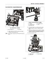
4.
If removing the power-trak from the mast use
the following steps;
(See illustration above)
a.
Remove the attach screws from the power-
trak guide bracket.
b.
Push the power track and cables down into
the mast past the hanger bracket slot in the
side of the mast.
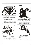
5.
At the top of the mast, carefully open the
bleeder valve on the top of the main hydraulic
cylinder #1 attached to the base frame.
NOTE:
While lifting the mast assembly out of the frame,
hydraulic cylinder #1 will still be attached to the
base frame, lift slowly straight up ONLY, do not
attempt to lift on an angle or the hydraulic cylinder
may be damaged.
NOTE:
Also when lifting the mast assembly, if you detached
the power-trak from the top of the mast it will need
to be lowered out the bottom of the mast as the
mast is lifted upwards.
6.
Carefully lift the mast assembly up out of the
frame far enough to gain access to the wire har-
ness connector for the lift down selenoid, and
the hydraulic lines connected to hydraulic cylin-
der #1, still attached to the base frame.
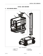
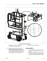
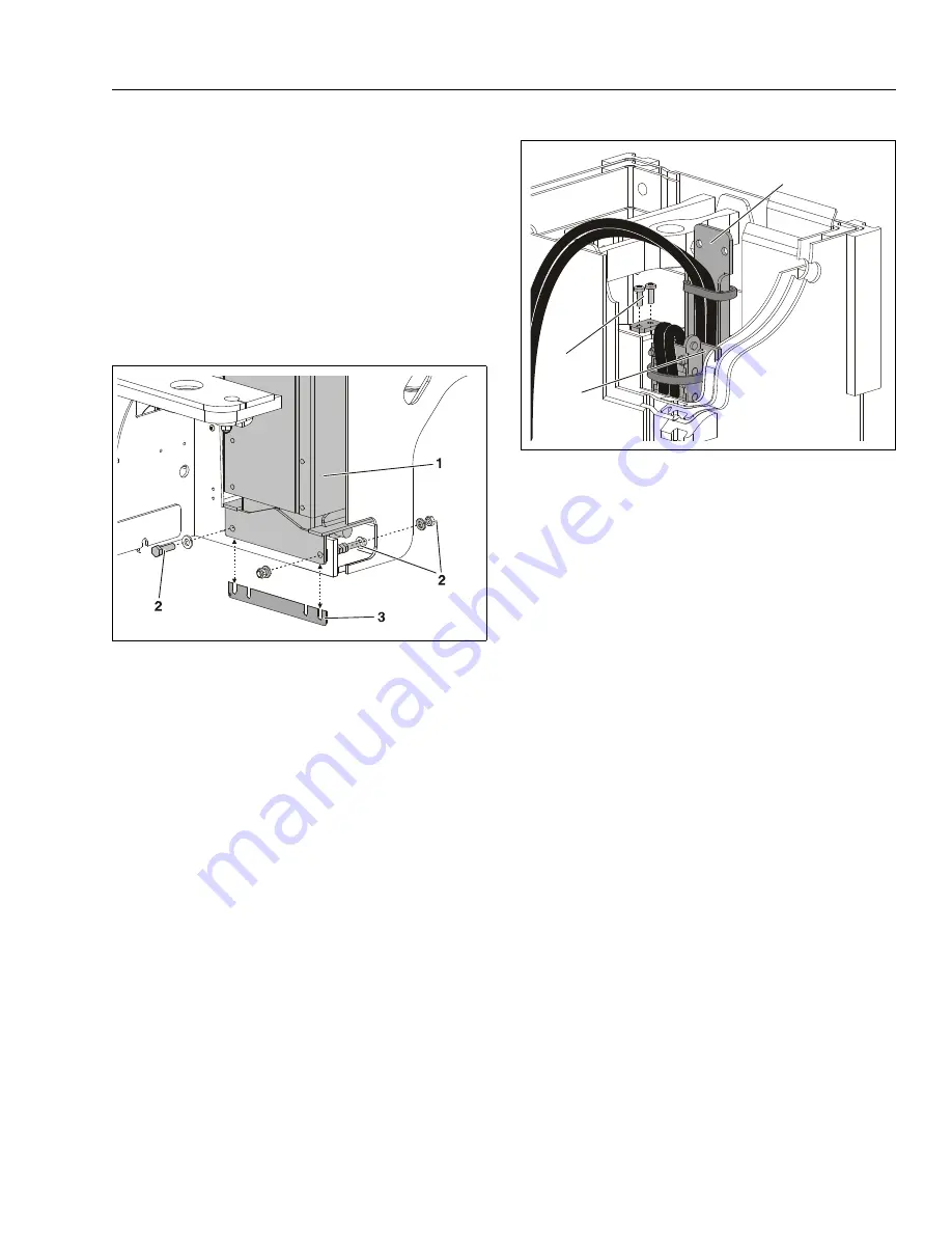
Figure 6-7. Mast Base Mounting Hardware
(Front of frame shown cutaway for illustrative purposes only)
1.
Mast Assembly
2.
Fastening Hardware
3.
20 Ga. (.0359 in.)- Mount-
ing Shim
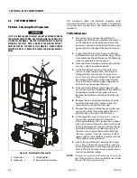
Figure 6-8. Power-Trak - Removal
1.
Attach Screws
2.
Power-Trak Hanger Bracket
(a)
3.
Power-Trak Guide (b)
4.
Hyd. Cyl. #1 Bleeder Valve
NOTE:
(a)Remove hanger bracket from slot in mast and push down into the mast.
(b)If platform has already been removed this will be hanging loose.
1
2
3
Summary of Contents for 1230ES
Page 1: ...AS NZS Service and Maintenance Manual Model s 1230ES P N 3121222 June 22 2017 ...
Page 2: ...NOTES ...
Page 24: ...SECTION 1 MACHINE SPECIFICATIONS 1 12 JLG Lift 3121222 NOTES ...
Page 32: ...SECTION 2 GENERAL SERVICE INFORMATION 2 8 JLG Lift 3121222 NOTES ...
Page 78: ...SECTION 4 BASE COMPONENTS 4 40 JLG Lift 3121222 NOTES ...
Page 104: ...SECTION 5 CONTROL COMPONENTS 5 26 JLG Lift 3121222 NOTES ...
Page 158: ...SECTION 8 DIAGNOSTIC TROUBLE CODES 8 22 JLG Lift 3121222 NOTES ...
Page 198: ...SECTION 9 GENERAL ELECTRICAL INFORMATION SCHEMATICS 9 40 JLG Lift 3121222 ...
Page 199: ...SECTION 9 GENERAL ELECTRICAL INFORMATION SCHEMATICS 3121222 JLG Lift 9 41 ...
Page 200: ...SECTION 9 GENERAL ELECTRICAL INFORMATION SCHEMATICS 9 42 JLG Lift 3121222 ...
Page 202: ...SECTION 9 GENERAL ELECTRICAL INFORMATION SCHEMATICS 9 44 JLG Lift 3121222 NOTES ...


