background image

SECTION 6 - TROUBLESHOOTING

3121228


JLG


Lift


6-45

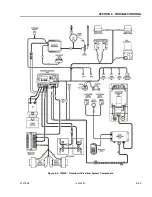
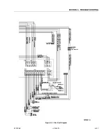
Figure 6-6.  10MSP - Overview of Electrical System Components.

Summary of Contents for 10msp

Page 1: ...Ser Service and Maintenance Ma vice and Maintenance Manual nual ANSI ANSI Model Model 10MSP 10MSP V Vertical Lift ertical Lift P N 3121228 P N 3121228 April 29 2 April 29 2013 013...

Page 2: ...NOTES NOTES...

Page 3: ...THE OWNER SAFETY IN THIS AREA IS THE RESPONSIBILITY OF THE OWNER OPERATOR OPERATOR B B HYD HYDRA RAULI ULIC S C SYST YSTEM EM SAF SAFETY ETY 1 1 It sh It should ould be p be particu articularly larly...

Page 4: ...ue of Manual December 23 2005 Manual Revised January 2 2005 Manual Revised January 6 2005 Manual Revised May 23 2006 Manual Revised October 4 2006 Manual Revised December 5 2007 Manual Revised Septemb...

Page 5: ...chine Overall 1 3 Platform Entry Height Floor to Platform Floor 1 3 Machine Ground Clearance 1 3 Machine Turning Radius Outside 1 3 1 4 TORQUE REQUIREMENTS 1 3 1 5 CYLINDER SPECIFICATIONS 1 3 1 6 SERI...

Page 6: ...ation 3 4 3 4 DRIVE ELEVATION CUT OUT SWITCH INSTALLATION 3 5 3 5 WHEEL DRIVE ASSEMBLY SERVICING 3 5 Roll and Leak Testing 3 5 Oil Type and Capacity 3 5 Drive Motor Brush Wear Warning Indication 3 6 W...

Page 7: ...3 Platform Control Console Installation 4 3 Platform Junction Box Install Remove 4 4 Junction Box to Ground Control Harness Remove Install 4 4 Platform Interlock Switch Circuit 4 5 4 3 GROUND CONTROL...

Page 8: ...ALGORITHM PROGRAMMING OF THE DELTA Q BATTERY CHARGER TO OPTIMIZE BATTERY LIFE AND MACHINE CYCLE TIMES THE USE OF NON APPROVED BATTER IES IN YOUR JLG EQUIPMENT MAY RESULT IN PERFORMANCE ISSUES OR BATTE...

Page 9: ...ice Classification GL 3 and sufficient chemical stabil ity for mobile hydraulic system service JLG Industries recommends Mobilfluid 424 hydraulic oil which has an SAE viscosity of 10W 30 and a viscosi...

Page 10: ...er Section CL BrushorSpray Inspect lubricateifdryorrusting KeytoLubricants MPG MultipurposeGrease HO HydraulicOil ISO Vggrade32 46 GEAROIL GoodQualityWormGearOil SAE90 AGMA 5 EPCompounded CL ChainLube...

Page 11: ...0 136 80 108 9 16 12 0 5625 0 1820 11600 110 149 80 108 120 163 98 133 18 0 5625 0 2030 12950 120 163 90 122 135 184 109 148 5 8 11 0 6250 0 2260 14400 150 203 110 149 165 224 135 183 18 0 6250 0 2560...

Page 12: ...imate and or conditions and depend ing on the location and use of the machine ing on the location and use of the machine T Table 2 1 Ma able 2 1 Maintenance and Inspection intenance and Inspection Req...

Page 13: ...eA As ss se em mb blly y 2 2 2 2 G Ge ea ar rB Bo ox xA As ss se em mb blly y D Dr ri iv ve eM Mo ot to or r B Br ru us sh he es s FUNCTIONS CONTROLS FUNCTIONS CONTROLS 7 7 P Plla at tf fo or rm mC Co...

Page 14: ...d Purchased used used d d Annually Annually no later than 13 months from the d no later than 13 months from the date of the ate of the prior prior inspection inspection GENERAL GENERAL O Op pe er ra a...

Page 15: ...nobstructed Cover all parts to keep them clean Be sure all parts are clean before they are installed New parts should remain in their containers until they are ready to be used Components Removal and...

Page 16: ...ays inspect that segment of chain that operates over a sheave As the chain flexes over the sheaves joints and plate edges very gradually wear Chain stretch can be measured using a manufacturers wear s...

Page 17: ...r protruding pins Keep chains lubricated Stress Corrosion Cracking The outside link plates which are heavily press fitted to the pins are particularly susceptible to stress corrosion cracking Like fat...

Page 18: ...25 hour DRIVE count down the machine will only drive in creep turtle drive mode and platform lift up will be disabled At this point cycling power on off will only repeat the final 10 second mode cycl...

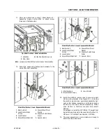
Page 19: ...on Right Side Shown 1 Wheel Drive Assembly 2 Frame Mounting Surface 3 Mounting Bolts Washers a 4 Drive Wheel 5 Wheel Mounting Lugs b NOTE Installation same for left and right drive motor a Apply Locti...

Page 20: ...the brake containment holes This will keep the brake housing in one piece 4 Cut the black wire tie not shown from the frame of the motor 5 Remove the 3 Brake Bolts 7 6 Remove the Brake Housing B1 and...

Page 21: ...CH CLIPS WHICH ARE FASTENED TO THE BRUSH CARRIER ASSEMBLY WITH SCREWS ITEM 5 RAISE THE COVER STRAIGHT UP REMOVE THE SCREWS THEN HINGE THE COVER UP SEE CENTER ILLUSTRATION AND PRY THE CLIPS OFF OF THE...

Page 22: ...iously with motor cover disassembly shown for reference only 1 3 4 Brush Assembly Remove Install 1 Brush Assembly a 2 Brush Carrier Socket 3 Brush Tab Slot 4 Brush Terminal Screw 5 Brush Attach Termin...

Page 23: ...ubes shown shortened for illustrative purposes only Pump Remove Install Requires removal of tank assembly and pump pick up tube 1 Pump Assembly 3 Motor to Pump Coupler 2 Pump Assembly Screws 4 Pump Sh...

Page 24: ...T MODIFY UNIT IN ANY WAY TO AFFECT STABIL ITY JLG MACHINES EQUIPPED WITH DELTA Q BATTERY CHARGERS ARE DESIGNED FOR THE BEST PERFORMANCE WITH OEM FAC TORY APPROVED BATTERIES APPROVED JLG REPLACEMENT BA...

Page 25: ...to keep button from turning Reattach wires to same terminals on new switch Power Selector Switch Installation 1 Selector Knob 3 Power Selector Switch 2 Nut 4 Align and insert tab into cover Note Reatt...

Page 26: ...Service and Maintenance Settings allow modi fication to machine personality settings such as lift speeds drive speeds as well as various switch polarity settings also enable various optional equipment...

Page 27: ...e then move on to Selecting Programmable Item to Adjust Selecting Programmable Item to Adjust 1 Use the Platform UP DOWN buttons 1 to scroll through the list of programmable items available to your pr...

Page 28: ...um mR Re ev ve er rs se eS Sp pe ee ed d P Plla at tf fo or rm mL Lo ow we er re ed d 2 20 0 1 1 1 10 00 0 2 2 M Ma ax xi im mu um mT Tu ur rn n S Sp pe ee ed d P Plla at tf fo or rm mL Lo ow we er r...

Page 29: ...odule Module Drive Lift Mo Drive Lift Mode Selector de Selector Switch Switch Horn But Horn Button Swit ton Switch ch Rear Rear Cover Cover Wiring Harness Wiring Harness Connector So Connector Socket...

Page 30: ...atformConsole CircuitBoardConnections PlatformConsole CircuitBoardConnections 1 1 Horn Switch C5 Horn Switch C5 2 2 Communications Cable to Communications Cable to Platform Junction Box Platform Junct...

Page 31: ...oving from console PlatformConsole Drive LiftModeSelectSwitch 1 Switch Assembly a 2 Locking Tabs Note a Remove rear cover unplug switch wire press tabs to remove 1 2 1 2 PlatformConsole HornSwitchInst...

Page 32: ...Switch Retainer Slots Note a Use a small straight blade screwdriver to extend the spring loaded retainer hooks 6 out and release the switch from the body 1 2 4 5 3 7 6 PlatformConsole JoystickInstalla...

Page 33: ...N 5 MAST COMPONENTS 3121228 JLG Lift 5 1 SECTION 5 MAST COMPONENTS 5 1 MAST COMPONENTS OVERVIEW Figure 5 1 Mast Components 1 Material Handling Tray 2 Platform Assembly 3 Mast Assembly 4 Platform Mast...

Page 34: ...ay Assembly 2 Tie Straps for Platform Console Harness 3 Countersunk Flat Head Socket Screws Washers and Locknuts 4 Hex Head Screws Wash ers and Locknuts a Platform shown without right side rails and p...

Page 35: ...will need to temporarily uncap the extend and return hydraulic lines to allow mast section 2 to and return hydraulic lines to allow mast section 2 to be extended in the next step Capture any hydraulic...

Page 36: ...oms o oms out ag ut against ainst the cylinder head the cylinder head 3 3 Comp Compress t ress the he he head ret ad retraini raining ri ng ring en ng enough ough to al to allow low the cylinder head...

Page 37: ...aces is unacceptable In the event that an unacceptable condition occurs the piston should be unacceptable condition occurs the piston should be replaced replaced Tube Assembly Tube Assembly Visually i...

Page 38: ...lation 1 Lift Down Valve a 2 Valve Solenoid b 3 Manual Release Assembly 4 O Ring with Backing Rings a 5 Valve O Ring a 6 Solenoid O Ring a Notes a Coat all o rings with clean hydraulic fluid before as...

Page 39: ...hardware to the top of mast Always install slide pad shims with slide pads inserted into the slide pad channels ends of mast sections even Apply ing Krytox spray JLG P N 3020041 onto the slide pads a...

Page 40: ...e sections together until ends are even 2 Insert slide pads into the slide pad channels at bot tom end of mast between section 1 and 2 one on each side of the mast with beveled surface facing out towa...

Page 41: ...astening and shimming the slide pad on the top left side of the mast install a sequence cable bracket against the mast under the flatwasher 11 Thread slide pad attaching bolts two 2 1 4 20UNC x 3 8 lo...

Page 42: ...the lower chain anchor bracket Loosely thread two 2 3 8 16UNC nuts onto the stud threads on each chain 7 Slide the anchor plate into the closed rail at the bot tom of mast section 4 and attach the an...

Page 43: ...the mast See Section 5 5 Platform 7 FT HEIGHT Limit Switch OPTION 14 The mast assembly is now complete and ready to install onto the base frame TopofMast Section 4 Slide PadInstallation 1 Slide Pads 2...

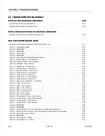
Page 44: ...Short Circuit 6 21 Code 12 Right Drive Motor Short Circuit 6 21 Code 13 Traction Module In Fold Back 6 21 Code 14 Pump Motor Disconnected 6 22 Code 15 Lift Down Valve Disconnected 6 22 Code 16 Lift Do...

Page 45: ...4 MAIN POWER CIRCUIT TROUBLESHOOTING Machine Will Not Power Up 6 35 MAST TROUBLESHOOTING Platform Will Not Lower Manually 6 36 Platform Lift Up And Down Jerky 6 36 Mast Noisy When Lifting And Lowering...

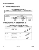
Page 46: ...Amperage Draw for Various Components COMPONENT AMPERAGE GroundControlModule 95Amps roomtemperaturewithratedload TractionControlModule LEVEL SURFACE 24V RATED LOAD 15 GRADE 24V RATED LOAD NO LOAD 24V 7...

Page 47: ...is in the drive speed cut back target raised the proximity switch then cuts back the machine drive speed When machine is in the drive speed cut back mode a turtle is mode a turtle is displayed on the...

Page 48: ...edinto anACoutlet anACoutlet G Go oT To oS St te ep p2 2 S Se ee e B Ba at tt te er ry y B Ba at tt te er ry y C Ch ha ar r ger Servicing ger Servicing Section3ofthisManual Section3ofthisManual 2 2 Is...

Page 49: ...allevelofthe machines restingsurfacein machines restingsurfacein boththeXandtheY boththeXandtheY directions Doessurfacecheckwithin directions Doessurfacecheckwithin machinespecifi machinespecifi catio...

Page 50: ...acrosspositive andnegative leadsinM2connec tor wiringharnessgoingtotheright drivemotor Isreadingwithin spec 1 to 3ohms Replace Traction Module GotoStep2 2 Repairorreplacerightdrivemotorwiring brusheso...

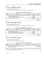
Page 51: ...egative lug No Voltage Thiscircuitshould beisolated RepairorReplace Componentsas Required GotoStep2 2 Checkforcontinuityofboththepinstoground NoGround Replace Traction ControlModule Table 6 13 Code 12...

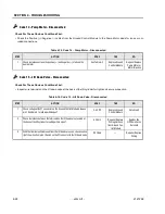
Page 52: ...eacrossthepositive andnegative studsonthe pumpmotor SeeTable6 2 ReplaceGround ControlModule RepairorReplace PumpMotoror Motor Brushes Table 6 16 Code 15 Lift Down Valve Disconnected STEP ACTION SPEC Y...

Page 53: ...7 PlugthecommunicationscableontheTractionControlModuletotheround socketontheoppositeendofthe module Doesthisfixproblem Done Replace GroundControl Module Table 6 35 Code 200 299 Platform Control Consol...

Page 54: ...between eachpowerrecycle Doesfaultclear Done GotoStep2 2 IsacodenumberdisplayingontheGroundControlStation Code 316 GotoStep3 Replace TractionControl Module Code 325 GotoStep5 3 Confirmthatbothinstalle...

Page 55: ...EP ACTION SPEC YES NO 1 Checkfor24VDCatthepositive andnegative mainpowercable connectionsontheGroundControlModule 24VDC GotoStep2 Replacethe175 AmpInlineFuseon the Positivepower cable 2 Checkcontinuit...

Page 56: ...SECTION 6 TROUBLESHOOTING 3121228 JLG Lift 6 45 Figure 6 6 10MSP Overview of Electrical System Components...

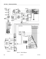
Page 57: ...SECTION 6 TROUBLESHOOTING 6 46 JLG Lift 3121228 Figure 6 7 Electrical Diagram 1870201_G Keyed Switch Removed for AustraliaSpec...

Page 58: ...SECTION 6 TROUBLESHOOTING 3121228 JLG Lift 6 47 Figure 6 3 Electrical Diagram 1870201 G...

Page 59: ...Figure 6 8 Hydraulic Diagram 2792684_A 1 Tank 5 Pressure Adjust Valve 9 Check Valve 2 Filter Screen 6 Extend Line 10 PressureCompensator FlowControlValve 3 Pump 7 Hydraulic Filter 11 Manual Decent Va...

Page 60: ......

Page 61: ...ce 33 0 5 53 88 31 70 33 0 5 53 88 31 79 JLG Deutschland GmbH Max Planck Str 21 D 27721 Ritterhude Ihlpohl Germany 49 0 421 69 350 20 49 0 421 69 350 45 JLG Equipment Services Ltd Rm 1107 Landmark Nor...

Reviews: