background image

7

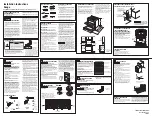
4. Add strain relief.

Style 1: Power supply cord strain relief

Assemble a UL listed strain relief in the opening.

Feed the power supply cord through the strain relief in the 
cord/conduit plate on bottom of range. Allow enough 
slack to easily attach the wiring to the terminal block.

Tighten strain relief screw against the power supply cord.

Style 2: Direct wire strain relief

Use Phillips screwdriver to remove screws and slide 
cord/conduit plate down and out.

Position cord/conduit plate as shown in the following 
illustration.

Replace cord/conduit plate and insert screws.

Assemble a UL listed conduit connector in the opening.

Feed the flexible conduit through the strain relief, allowing 
enough slack to easily attach wiring to the terminal block.

Tighten strain relief screw against the flexible conduit.

5. Replace back panel and screws on rear of range.

6. Complete installation following instructions for your type of 

electrical connection:

4-wire (recommended)

3-wire (if 4-wire is not available)

A. UL listed strain relief

A

A. Removable retaining nut
B. Strain relief

A

B

Summary of Contents for JER8895BAS - 30" Electric Double Oven Range

Page 1: ...injured if you don t immediately You can be killed or seriously injured if you don t follow All safety messages will tell you what the potential hazard is tell you how to reduce the chance of injury a...

Page 2: ...that projects horizontally a minimum of 5 12 7 cm beyond the bottom of the cabinets Cabinet opening dimensions that are shown must be used Given dimensions are minimum clearances The floor anti tip b...

Page 3: ...retardant millboard covered with not less than No 28 MSG sheet steel 0 015 0 4 mm stainless steel 0 024 0 6 mm aluminum or 0 020 0 5 mm copper 30 76 2 cm minimum clearance between the top of the cooki...

Page 4: ...r circuit breaker box through flexible or nonmetallic sheathed copper or aluminum cable See Electrical Connection Allow 2 to 3 ft 61 0 cm to 91 4 cm of slack in the line so that the range can be moved...

Page 5: ...maximum of 1 2 5 cm A minimum of 5 mm is needed to engage the anti tip bracket NOTE If height adjustment is made when range is standing tilt the range back to adjust the front legs then tilt forward...

Page 6: ...n and toward you to remove cover 3 Remove plastic tag holding three 10 32 hex nuts from the middle post of the terminal block A 12 x 1 screws B Anti tip bracket A B A 12 x 1 screws B Anti tip bracket...

Page 7: ...nduit plate down and out Position cord conduit plate as shown in the following illustration Replace cord conduit plate and insert screws Assemble a UL listed conduit connector in the opening Feed the...

Page 8: ...rminal block posts with 10 32 hex nuts 7 Securely tighten hex nuts NOTE For power supply cord replacement only use a power cord rated at 250 volts minimum 40 amps or 50 amps that is marked for use wit...

Page 9: ...nnected directly to the fuse disconnect or circuit breaker box Depending on your electrical supply make the required 3 wire or 4 wire connection 1 Strip outer covering back 3 7 6 cm to expose wires St...

Page 10: ...s 7 Connect line 1 black and line 2 red wires to the outer terminal block posts with 10 32 hex nuts 8 Securely tighten hex nuts 9 Replace terminal block access cover 3 wire connection Direct Wire Use...

Page 11: ...for satisfactory baking conditions CompleteInstallation 1 Check that all parts are now installed If there is an extra part go back through the steps to see which step was skipped 2 Check that you have...

Page 12: ...nge forward 3 Complete cleaning or maintenance 4 Check that anti tip bracket is installed Look for the anti tip bracket securely attached to floor or wall Slide range back so rear range foot is under...

Reviews: