


alent meeting standards SAE J1703 and DOT 3. Do
not use any other type of fluid.
CLUTCH FLUID LEVEL
The clutch fluid reservoir, master cylinder, slave
cylinder and fluid lines are pre-filled with fluid at
the factory during assembly operations.
The hydraulic system should not require additional
fluid under normal circumstances. In fact, the reser-
voir fluid level will actually increase as normal
clutch wear occurs. For this reason, it is impor-
tant to avoid overfilling, or removing fluid from
the reservoir.
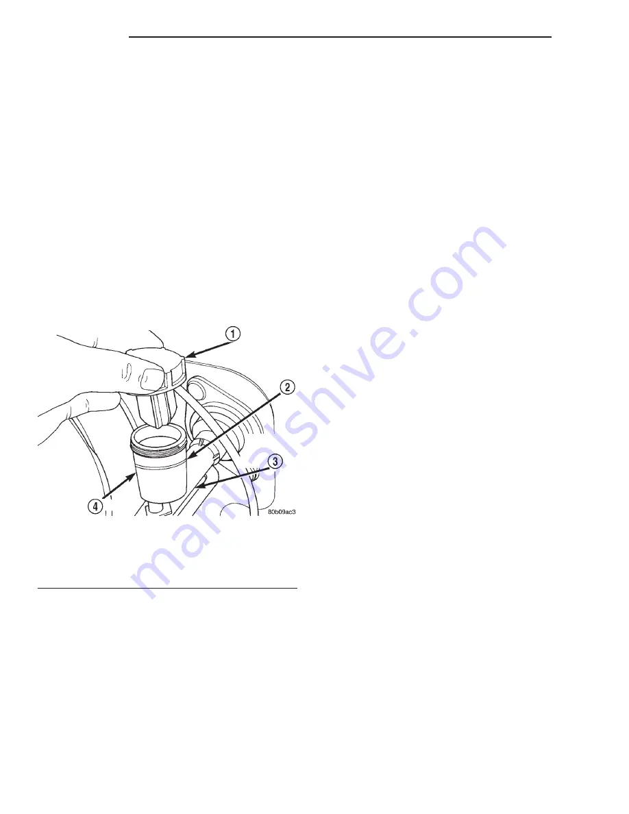
Clutch fluid level is checked at the master cylinder
reservoir (Fig. 9). An indicator ring is provided on the
outside rim of the reservoir.
Be sure to wipe the reservoir and cover clean
before removing the cover. This will avoid having dirt
or foreign material fall into the reservoir during a
fluid level check.
FLYWHEEL
Inspect the flywheel whenever the clutch disc,
cover and housing are removed for service. Check
condition of the flywheel face, hub, ring gear teeth,
and flywheel bolts.
Minor scratches, burrs, or glazing on the flywheel
face can be reduced with 180 grit emery cloth. How-
ever, the flywheel should be replaced if the disc con-
tact surface is severely scored, heat checked, cracked,
or obviously worn.
Flywheel machining is not recommended. The fly-
wheel surface is manufactured with a unique contour
that would be negated by machining. However,
cleanup of minor flywheel scoring can be performed
by hand with 180 grit emery, or with surface grind-
ing equipment. Replace the flywheel if scoring is
deeper than 0.0762 mm (0.003 in.).
Heavy stock removal by grinding is not recom-
mended. Excessive stock removal can result in fly-
wheel cracking or warpage after installation. It can
also weaken the flywheel and interfere with proper
clutch release.
Check flywheel runout if misalignment is sus-
pected. Runout should not exceed 0.08 mm (0.003
in.). Measure runout at the outer edge of the fly-
wheel face with a dial indicator. Mount the dial indi-
cator on a stud installed in place of one of the clutch
housing attaching bolts.
Clean the crankshaft flange before mounting the
flywheel. Dirt and grease on the flange surface may
cock the flywheel causing excessive runout.
Check condition of the flywheel hub and attaching
bolts. Replace the flywheel if the hub exhibits cracks
in the area of the attaching bolt holes.
Install new attaching bolts whenever the flywheel
is replaced and use Mopar
t
Lock N’ Seal, or Loctite
242 on the replacement bolt threads.
Recommended flywheel bolt torques are:
•
142 N·m (105 ft. lbs.) for 6-cylinder flywheels
•
95 N·m (70 ft. lbs.) for 4-cylinder flywheels
Inspect the teeth on the starter ring gear. If the
teeth are worn or damaged, the flywheel should
be replaced as an assembly. This is the recom-
mended and preferred method of repair.
In cases where a new flywheel is not readily avail-
able, a replacement ring gear can be installed. How-
ever, the following precautions must be observed to
avoid damaging the flywheel and replacement gear.
(1) Mark position of the old gear for alignment ref-
erence on the flywheel. Use a scriber for this pur-
pose.
(2) Wear protective goggles or approved safety
glasses. Also wear heat resistent gloves when han-
dling a heated ring gear.
(3) Remove the old gear by cutting most of the way
through it (at one point) with an abrasive cut-off
wheel. Then complete removal with a cold chisel or
punch.
(4) The ring gear is a shrink fit on the flywheel.
This means the gear must be expanded by heating in
order to install it. The method of heating and
expanding the gear is extremely important.
Every surface of the gear must be heated at the same
time to produce uniform expansion. An oven or simi-
lar enclosed heating device must be used. Tempera-
ture required for uniform expansion is approximately
375° F.
Fig. 9 Clutch Master Cylinder Reservoir And Cap
1 – CAP
2 – FILL LINE
3 – CLUTCH MASTER CYLINDER
4 – RESERVOIR
6 - 10
CLUTCH
XJ
SERVICE PROCEDURES (Continued)
Summary of Contents for Cherokee 2000
Page 4: ......
Page 36: ......
Page 96: ...Fig 105 Gear Tooth Contact Patterns 3 60 TUBE 181 AND 186 FBI AXLE XJ ADJUSTMENTS Continued...
Page 100: ...Installer D 144 Installer W 262 3 64 TUBE 181 AND 186 FBI AXLE XJ SPECIAL TOOLS Continued...
Page 134: ...Fig 79 Gear Tooth Contact Patterns 3 98 194 RBI AXLE XJ ADJUSTMENTS Continued...
Page 166: ...Fig 59 Gear Tooth Contact Patterns 3 130 8 1 4 REAR AXLE XJ ADJUSTMENTS Continued...
Page 215: ...Fig 8 Clutch Components And Inspection XJ CLUTCH 6 5 DIAGNOSIS AND TESTING Continued...
Page 226: ......
Page 231: ...Fig 8 Clutch Components And Inspection XJ CLUTCH 6 5 DIAGNOSIS AND TESTING Continued...
Page 242: ......
Page 284: ......
Page 300: ......
Page 372: ......
Page 376: ......
Page 382: ......
Page 404: ......
Page 412: ......
Page 416: ......
Page 430: ......
Page 444: ......
Page 448: ......
Page 468: ......
Page 482: ......
Page 500: ......
Page 508: ......
Page 520: ......
Page 526: ......
Page 532: ......
Page 540: ......
Page 550: ......
Page 647: ...Fig 16 2 5L Engine XJ 8W 90 CONNECTOR LOCATIONS 8W 90 23 DESCRIPTION AND OPERATION Continued...
Page 648: ...Fig 17 4 0L Engine 8W 90 24 8W 90 CONNECTOR LOCATIONS XJ DESCRIPTION AND OPERATION Continued...
Page 649: ...Fig 18 4 0L Engine XJ 8W 90 CONNECTOR LOCATIONS 8W 90 25 DESCRIPTION AND OPERATION Continued...
Page 662: ...Fig 31 Liftgate 8W 90 38 8W 90 CONNECTOR LOCATIONS XJ DESCRIPTION AND OPERATION Continued...
Page 666: ......
Page 810: ......
Page 826: ...Fig 6 Frame Dimensions 13 8 FRAME AND BUMPERS XJ SPECIFICATIONS Continued...
Page 828: ......
Page 1316: ......
Page 1328: ......
Page 1353: ...Fig 3 Hood Components XJ BODY 23 25 REMOVAL AND INSTALLATION Continued...
Page 1396: ...WELD LOCATIONS UPPER COWL 23 68 BODY XJ SPECIFICATIONS Continued...
Page 1397: ...UPPER COWL XJ BODY 23 69 SPECIFICATIONS Continued...
Page 1398: ...COWL 23 70 BODY XJ SPECIFICATIONS Continued...
Page 1399: ...A PILLAR XJ BODY 23 71 SPECIFICATIONS Continued...
Page 1400: ...A PILLAR 23 72 BODY XJ SPECIFICATIONS Continued...
Page 1401: ...A PILLAR XJ BODY 23 73 SPECIFICATIONS Continued...
Page 1402: ...A PILLAR 23 74 BODY XJ SPECIFICATIONS Continued...
Page 1403: ...B PILLAR XJ BODY 23 75 SPECIFICATIONS Continued...
Page 1404: ...D PILLAR 23 76 BODY XJ SPECIFICATIONS Continued...
Page 1405: ...FUEL FILLER OPENING XJ BODY 23 77 SPECIFICATIONS Continued...
Page 1406: ...CARGO AREA FLOOR PAN 23 78 BODY XJ SPECIFICATIONS Continued...
Page 1407: ...ROOF AND D PILLAR XJ BODY 23 79 SPECIFICATIONS Continued...
Page 1408: ...LIFTGATE OPENING 23 80 BODY XJ SPECIFICATIONS Continued...
Page 1409: ...ROOF XJ BODY 23 81 SPECIFICATIONS Continued...
Page 1410: ...ROOF 23 82 BODY XJ SPECIFICATIONS Continued...
Page 1411: ...FRAME RAIL XJ BODY 23 83 SPECIFICATIONS Continued...
Page 1412: ...FRAME RAIL 23 84 BODY XJ SPECIFICATIONS Continued...
Page 1413: ...FRAME RAIL XJ BODY 23 85 SPECIFICATIONS Continued...
Page 1414: ...FRAME RAIL 23 86 BODY XJ SPECIFICATIONS Continued...
Page 1415: ...REINFORCEMENT XJ BODY 23 87 SPECIFICATIONS Continued...
Page 1416: ...FRONT INNER FENDER 23 88 BODY XJ SPECIFICATIONS Continued...
Page 1417: ...FRONT INNER FENDER AND RADIATOR CLOSURE PANEL XJ BODY 23 89 SPECIFICATIONS Continued...
Page 1418: ...REINFORCEMENT 23 90 BODY XJ SPECIFICATIONS Continued...
Page 1419: ...FRONT FENDER XJ BODY 23 91 SPECIFICATIONS Continued...
Page 1420: ...BODY SIDE 23 92 BODY XJ SPECIFICATIONS Continued...
Page 1421: ...REAR WHEELHOUSE XJ BODY 23 93 SPECIFICATIONS Continued...
Page 1422: ...REAR INNER WHEELHOUSE 23 94 BODY XJ SPECIFICATIONS Continued...
Page 1423: ...BODY SIDE XJ BODY 23 95 SPECIFICATIONS Continued...
Page 1424: ...BODY SIDE 23 96 BODY XJ SPECIFICATIONS Continued...
Page 1425: ...BODY SIDE XJ BODY 23 97 SPECIFICATIONS Continued...
Page 1426: ...BODY SIDE 23 98 BODY XJ SPECIFICATIONS Continued...
Page 1427: ...BODY SIDE XJ BODY 23 99 SPECIFICATIONS Continued...
Page 1428: ...BODY SIDE 23 100 BODY XJ SPECIFICATIONS Continued...
Page 1429: ...UNDERBODY XJ BODY 23 101 SPECIFICATIONS Continued...
Page 1430: ...UNDERBODY 23 102 BODY XJ SPECIFICATIONS Continued...
Page 1431: ...UNDERBODY XJ BODY 23 103 SPECIFICATIONS Continued...
Page 1432: ...UNDERBODY 23 104 BODY XJ SPECIFICATIONS Continued...
Page 1433: ...UNDERBODY XJ BODY 23 105 SPECIFICATIONS Continued...
Page 1434: ...UNDERBODY 23 106 BODY XJ SPECIFICATIONS Continued...
Page 1435: ...UNDERBODY XJ BODY 23 107 SPECIFICATIONS Continued...
Page 1436: ...UNDERBODY 23 108 BODY XJ SPECIFICATIONS Continued...
Page 1437: ...UNDERBODY XJ BODY 23 109 SPECIFICATIONS Continued...
Page 1438: ...UNDERBODY 23 110 BODY XJ SPECIFICATIONS Continued...
Page 1439: ...UNDERBODY XJ BODY 23 111 SPECIFICATIONS Continued...
Page 1440: ...BODY SEALING LOCATIONS APPLICATION METHODS 23 112 BODY XJ SPECIFICATIONS Continued...
Page 1441: ...COWL AND DASH PANEL XJ BODY 23 113 SPECIFICATIONS Continued...
Page 1442: ...DASH PANEL AND FLOOR PAN 23 114 BODY XJ SPECIFICATIONS Continued...
Page 1443: ...FLOOR PAN XJ BODY 23 115 SPECIFICATIONS Continued...
Page 1444: ...REAR INNER WHEELHOUSE 23 116 BODY XJ SPECIFICATIONS Continued...
Page 1445: ...FRONT INNER WHEELHOUSE XJ BODY 23 117 SPECIFICATIONS Continued...
Page 1446: ...BODY SIDE 23 118 BODY XJ SPECIFICATIONS Continued...
Page 1447: ...BODY SIDE XJ BODY 23 119 SPECIFICATIONS Continued...
Page 1448: ...BODY SIDE 23 120 BODY XJ SPECIFICATIONS Continued...
Page 1449: ...ROOF PANEL XJ BODY 23 121 SPECIFICATIONS Continued...
Page 1450: ...FUEL FILLER HOUSING 23 122 BODY XJ SPECIFICATIONS Continued...
Page 1451: ...LIFTGATE OPENING XJ BODY 23 123 SPECIFICATIONS Continued...
Page 1452: ...STRUCTURAL ADHESIVE LOCATIONS LEFT QUARTER PANEL 23 124 BODY XJ SPECIFICATIONS Continued...
Page 1453: ...REAR WHEELHOUSE XJ BODY 23 125 SPECIFICATIONS Continued...
Page 1454: ...ROOF BOWS 23 126 BODY XJ SPECIFICATIONS Continued...
Page 1464: ......
Page 1512: ......
Page 1528: ......


