Operation and Control Instructions 35
Protocol for the Enhanced Parallel Interface
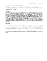
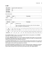
The read and write cycles follow a mechanism that tightly couples the control signals (SOP and
STROBE lines on the master side and BUSY line on the slave side) to provide flow control. These
cycles are defined as follows.
Read Cycle
The read cycle refers to the bus master reading bytes from the SKB slave (Figure 11). In this mode,
the master ensures that the R/W line is pulled high. The master then toggles the /SOP line from the
high to the low state, which signals the SKB switch to place the first data byte on the data lines. The
BUSY line is held high to indicate to the master that a valid byte has been placed on the data lines.
To indicate that the master has completed the read, the /STROBE line transitioned to low. The SKB
switch subsequently pulls the BUSY line low to signal that the data acknowledgment has been
received. The master then sets the STROBE to high. The BUSY transitions to high to indicate to the
master when the next byte has been placed on the data lines. Upon completion of the last data byte
transmission, the master resets the /SOP line from the low to the high state to indicate the end of the
data packet.
Write Cycle
The write cycle refers to the bus master writing bytes to the SKB slave (Figure 12). In this mode, the
master ensures that the R/W line is pulled low. The master then toggles the /SOP line from high to
low, which indicates the beginning of a new packet. Binary byte data is subsequently placed on the
data lines /D0 to /D7 and entered by use of the /STROBE line. After each STROBE, the BUSY line is
held high until the SKB switch is ready to receive the next data byte. Upon completion of the last data
byte transmission, the /SOP line is toggled from low to high, indicating the end of the data packet.
Please refer to the Application note section for details and examples of Enhanced parallel implemen-
tation.
Summary of Contents for SKB Series
Page 1: ...SKB SERIES FIBEROPTIC SWITCH MODULE User Manual ...
Page 2: ...ii 10109002 Rev 001 August 2001 2001 JDS Uniphase All rights reserved ...
Page 4: ...iv ...
Page 11: ...7 Contents ...
Page 13: ...9 List of Figures ...
Page 15: ...11 List of Tables ...
Page 19: ...4 Safety Information Instructions and Symbols ...
Page 25: ...10 Introduction ...
Page 53: ...38 Operation and Control Instructions ...
Page 91: ...76 Commands ...
Page 111: ...96 Application Notes ...
Page 113: ...98 Service ...

