


20 Installation and Physical Interface
1. The GND (shield) signal lines should be connected to the common ground.
2. The power pins are allocated on the assumption of Simplex operation for SK/SP emulation purposes.
These pins should not be used if the user elects to power the unit using the 4x1 power connector.
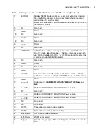
25
/STROBE
/STROBE input, active low: a high to low pulse = read data lines;
a high = ignore state of data lines. This line is internally pulled high
via 10 K ohm resistor to 5 VDC. For the SK emulation the home line
is also read in via the STROBE signal
26
D5
Data line 5
27
GND
1
Shield
28
D6
Data line 6
29
GND
1
Shield
30
/HOME
Home input: low sends the switch to the home position in Simplex
(SK emulation) mode (i.e. this acts the same as the /RESET line
defined in the SK/SP manual when the unit is wired as per this table)
31
GND
1
Shield
32
DGND
2
Digital ground, RESERVED FOR SK/SP EMULATION/ Power on
2x25
33
+5 VDC
2
RESERVED FOR SK/SP EMULATION/ Power on 2x25
34
D7
Data line 7
35
+5 VDC
2
RESERVED FOR SK/SP EMULATION/ Power on 2x25
36
+5 VDC
2
RESERVED FOR SK/SP EMULATION/ Power on 2x25
37
NC
No connect
38
NC
No connect
Table 3: Pin Assignment: Enhanced Parallel Interface (on 25x2 IDE connector)
PIN
SIGNAL
DESCRIPTION
1-8
NC
No connect
9
/SOP
Start of packet
10
R/W
Read/write
11
/RESET
This is a micro controller unit (MCU) reset
12
RESERVED
For internal use only
13
GND
1
Shield
14
DGND
2
Digital ground, RESERVED FOR SK/SP EMULATION/ Power on
2x25
15
BUSY
Busy output: low=idle, high= switching
16
D0
Data line 0
Table 2: Pin Assignment: Simplex (SK/SP Emulation) Parallel Interface (on 25x2 IDE connector) (Continued)
Summary of Contents for SKB Series
Page 1: ...SKB SERIES FIBEROPTIC SWITCH MODULE User Manual ...
Page 2: ...ii 10109002 Rev 001 August 2001 2001 JDS Uniphase All rights reserved ...
Page 4: ...iv ...
Page 11: ...7 Contents ...
Page 13: ...9 List of Figures ...
Page 15: ...11 List of Tables ...
Page 19: ...4 Safety Information Instructions and Symbols ...
Page 25: ...10 Introduction ...
Page 53: ...38 Operation and Control Instructions ...
Page 91: ...76 Commands ...
Page 111: ...96 Application Notes ...
Page 113: ...98 Service ...