31
GSM/GPRS/EDGE SIGNAL ANALYZER
JD7105B Base Station Analyzer
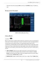
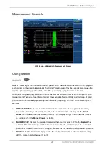
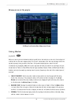
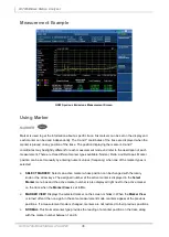
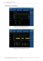
Measurement Example
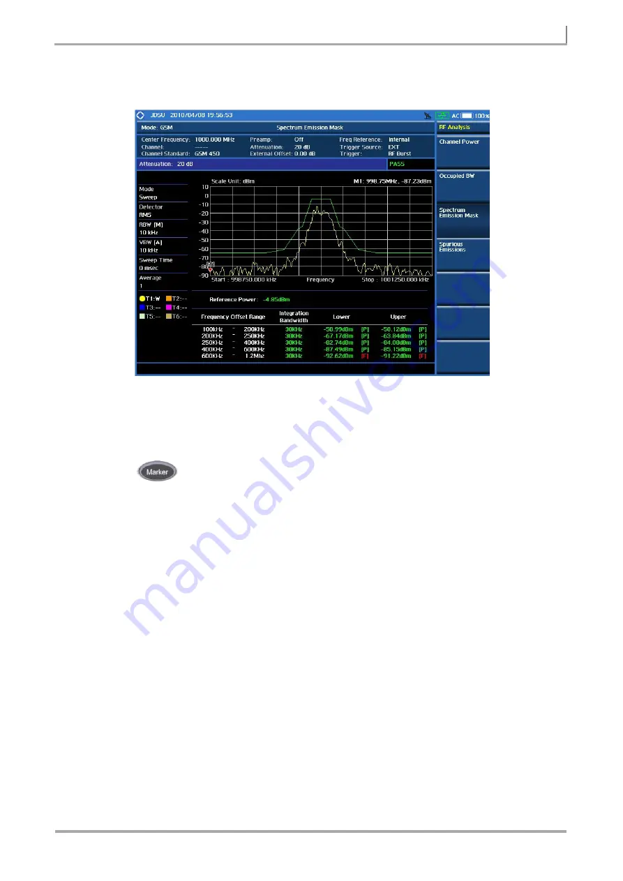
GSM Spectrum Emission Mask Measurement Screen
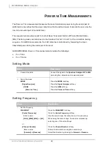
Using Marker
MARKER
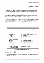
Marker is used to get the information about a specific trace. Six markers can be set on the display and
each marker can be used independently. The X and Y coordinates of the trace are displayed when the
marker is placed on any position of the trace. The position displaying the marker’s X and Y
coordinates may be slightly different for each measurement mode and refer to the description of each
measurement. There are three different marker types available: Normal, Delta, and Delta pair. Marker
position can be set manually by entering numeric values (frequency) when one of the marker types is
selected.
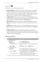
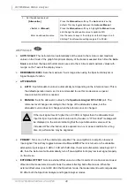
SELECT MARKER:
Selects an active marker whose position can be changed with the rotary
knob or the arrow keys. The assigned number of the active marker is displayed in the
Select
Marker
menu box and the active marker number is also displayed right next to the active marker
on the trace when the
Marker View
is set to
On
.
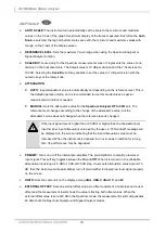
MARKER VIEW:
Displays the selected marker on the screen or hides it. When the
Marker View
is turned off and then on again in the same measurement mode, markers appear at the previous
positions. If a measurement mode is changed, markers are not restored to their previous positions.
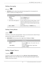
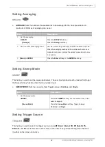
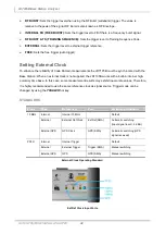
NORMAL:
This Normal marker type provides the reading of a marker position on the trace along
with the marker number between 1 and 6.

