


Chapter 5
Power meter, VFL (Visual Fault Locator) & Talkset
VFL Function
User Manual
790000002/00
31
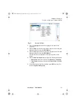
2
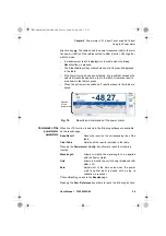
In the
Results
page, press the
Powermeter Config.
>
Zero
soft key
and validate.
Carrying out the reference measurement
1
Fix the adapter corresponding to the jumper to the optical connector
of the power meter.
2
Connect the jumper between the input of the power meter and the
output of the source.
3
Configure the same wavelength on the source and the power meter.
The power measured is displayed in the results page of the power
meter.
4
Press the
Pow Reference
>
Standard Ref
soft keys to save the
result displayed as reference value.
Measurements on the fiber under test
After defining the reference value, proceed as follows to make the
measurement:
1
Fix the jumpers and connectors needed to connect the fiber to be
tested between the source output and the power meter input.
2
In the set-up menu, select dB units.
3
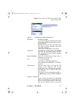
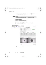
The power displayed in the Power Meter window corresponds to the
optical loss of the link tested. It can be displayed in the table (see
VFL Function
VFL connector
The type of optical connector used for the VFL source is UPP (Universal
Push Pull), which is compatible with all diameter 2.5 mm connectors (FC,
SC, ST, DIN, E2000, etc.)
to visualize the VFL connector.
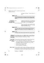
Visual Fault
Locator
function (VFL)
This function is used to emit a red light signal of frequency 1 Hz or in
continuous mode into a fiber to detect any defects in the dead zone of the
reflectometer, or to identify it.
This function is suitable for short fibers (length < 5 km) or the first few
metres of a long fiber.
2000 Platform English rev00.book Page 31 Lundi, 20. juin 2011 1:47 13


